Configuration CP3002
Page 4 - 16 ID 1042-9252, Rev. 2.0
P R E L I M I N A R Y
4.3.14 LED Configuration Register (LCFG)
The LED Configuration Register holds a series of bits defining the onboard configuration for the
front panel General Purpose LEDs.
1)
In uEFI BIOS POST mode, the LED0..3 build a binary vector to display uEFI BIOS POST
code during the pre-boot phase. In doing so, the higher 4-bit nibble of the 8-bit uEFI BIOS
POST code is displayed followed by the lower nibble followed by a pause. uEFI BIOS POST
code is displayed in general in green color.
LED3: POST bit 3 and bit 7 (green)
LED2: POST bit 2 and bit 6 (green)
LED1: POST bit 1 and bit 5 (green)
LED0: POST bit 0 and bit 4 (green)
For further information reading the 8-bit uEFI BIOS POST Code, refer to Chapter 2.11.1.2,
“General Purpose LEDs”.
2)
Configured for General Purpose Mode, the LEDs are dedicated to functions as follows:
LED3: LED3 controlled by HOST (red/green/red+green)
LED2: LED2 controlled by HOST (red/green/red+green)
LED1: LED1 controlled by HOST (red/green/red+green)
LED0: LED0 controlled by HOST (red/green/red+green)
Beside the configurable functions described above, the LED0..3 fulfill also a basic debug func-
tion during the power-up phase as long as the first access to Port 80 is processed. If an LED
lights red and stays red, than a basic error is present on the board. The following debug func-
tions are defined and displayed during this initialization phase.
LED3: Power good status not reached (red)
LED2: Processor catastrophic error (red)
LED1: Hardware reset active/not deactivated (red)
LED0: uEFI BIOS boot failure (red)
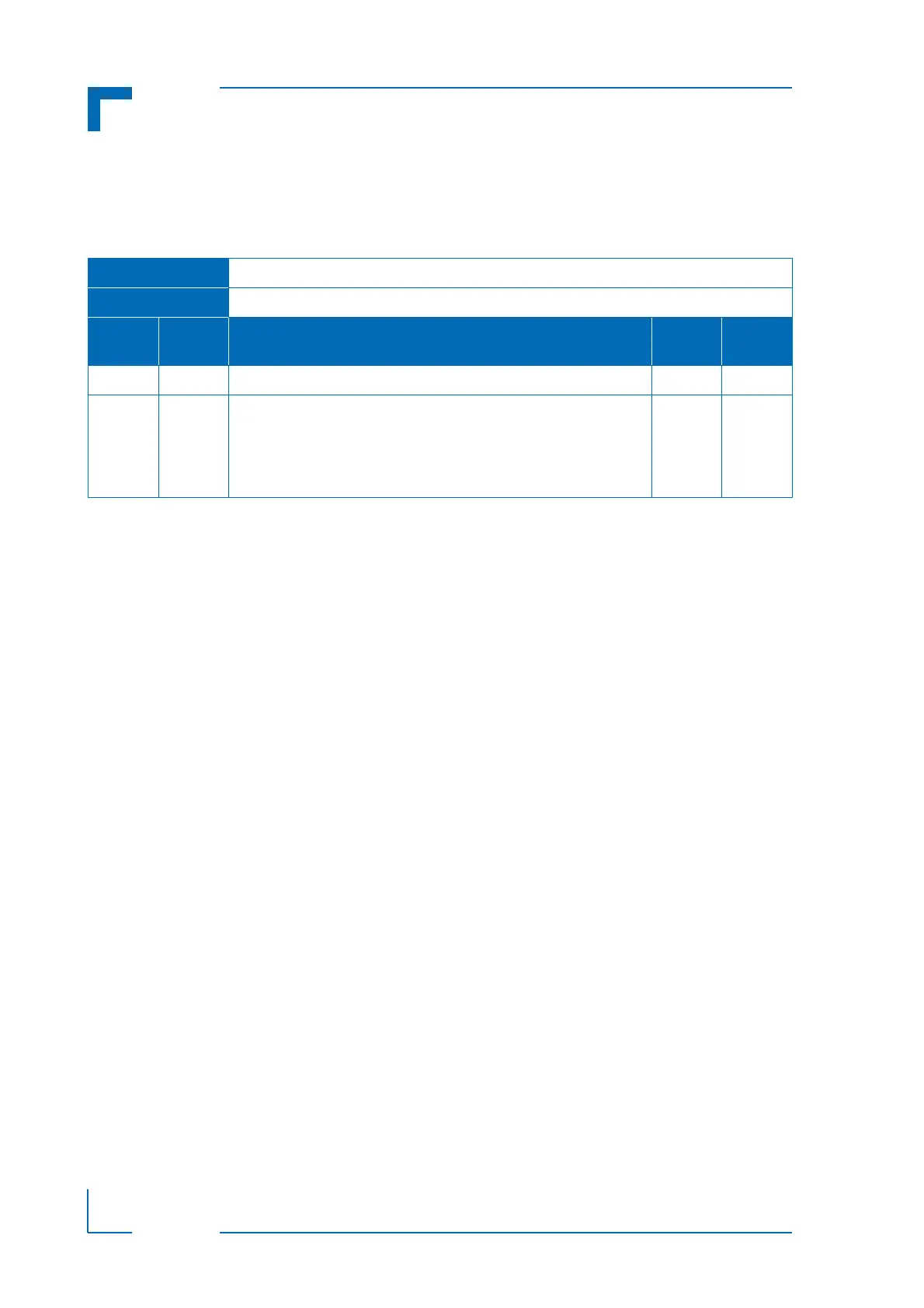
Table 4-16: LED Configuration Register (LCFG)
REGISTER NAME LED CONFIGURATION REGISTER (LCFG)
ADDRESS 0x290
BIT NAME DESCRIPTION
RESET
VALUE
ACCESS
7 - 4 Res. Reserved 0000 R
3 - 0 LCON LED0..3 configuration:
0000 = POST
1)
0001 = General Purpose Mode
2)
0010 - 1111 = Reserved
0000 R/W