Configuration CP3002
Page 4 - 4 ID 1042-9252, Rev. 2.0
P R E L I M I N A R Y
To clear the uEFI BIOS settings and the passwords, proceed as follows:
1. Set DIP switch SW1, switch 4, to the ON position.
2. Apply power to the system.
3. Wait 30 seconds and then remove power from the system. During this time period no
messages are displayed.
4. Set DIP switch SW1, switch 4, to the OFF position.
4.2 Jumper Description
The CP3002 has two solder jumpers, one reserved for factory use (JP1) and one reserved for
future use (JP2).
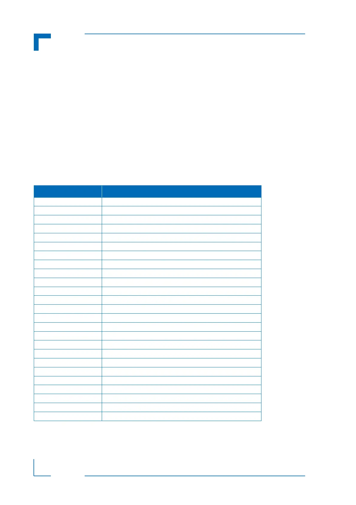
4.2.1 I/O Address Map
The following table indicates the CP3002-specific registers.
Table 4-2: I/O Address Map
ADDRESS DEVICE
0x080 uEFI BIOS POST Code Low Byte Register (POSTL)
0x081 uEFI BIOS POST Code High Byte Register (POSTH)
0x082 - 0x083 Reserved
0x084 Debug Low Byte Register (DBGL)
0x085 Debug High Byte Register (DBGH)
0x280 Status Register 0 (STAT0)
0x281 Status Register 1 (STAT1)
0x282 Control Register 0 (CTRL0)
0x283 Control Register 1 (CTRL1)
0x284 Device Protection Register (DPROT)
0x285 Reset Status Register (RSTAT)
0x286 Board Interrupt Configuration Register (BICFG)
0x287 Status Register 2 (STAT2)
0x288 Board ID High Byte Register (BIDH)
0x289 Board and PLD Revision Register (BREV)
0x28A Geographic Addressing Register (GEOAD)
0x28B Reserved
0x28C Watchdog Timer Control Register (WTIM)
0x28D Board ID Low Byte Register (BIDL)
0x28E - 0x28F Reserved
0x290 LED Configuration Register (LCFG)
0x291 LED Control Register (LCTRL)
0x292 General Purpose Output Register (GPOUT)
0x293 General Purpose Input Register (GPIN)
0x294 - 0x29F Reserved