18
Reverse
Screws (M4)
Screws
(M4)
Cord
holder
Reverse
Anti-tipping
Bracket
Stabilizing felt
Stabilizing felt
If you are concerned about
instability at the installation
location after assembly,
attach the felt to stabilize
the digital piano.
11. Connect the pedal cord and the speaker cord to the con-
nectors on the rear of the C1/C1 Air’s connector box.
Whenconnectingthepedalcordandthespeakercord,ob-
servethecorrectorientationsoftheconnectors.
Thepedalcordorthespeakercordcanbedetachedfrom
theconnectorwithitslockingtabhelddown.
Cord
holder
Speaker cord
Pedal cord
Locking tab
12. Use the cord holder to hold the pedal cord.
Aftersecuringthecordwiththecordholder,ensurethat
excesspressureisnotappliedtotheconnectors.
13. Connect the dedicated cord to the AC adapter. Then, plug
the AC adapter into the DC 24V connector, and wrap the
cord around the cord hook of the piano. For details, refer
to “Connecting the Power” on page 5.
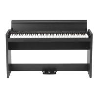
14. Place the C1/C1 Air where you intend to use it. Makesure
to place it in a safe location where the oor is atand
stable.
When seing the digital piano in place, make sure
thatthestanddoesnotrestontheACadaptercableor
pedalcable.
For greater safety, be sure to aach the anti-tipping
bracketstotherearoftheleftandrightsidepanels.
Check following assembly
□ Are any parts left over?
If any parts are left over, carefully review the assembly
proceduretoseewherethosepartsshouldhavebeenused.
□ Makesurethatallscrewsaretight.
□ Dependingontheconditionoftheoorattheinstallation
location, the digital piano mayshake back and forth. In
thatcase,aachoneortwopiecesofstabilizingfelttothe
boomoftheanti-tippingbracketsinordertoreducethe
shaking(seethediagramforstep10).
Speaker cord
Dent
Bracket (A)
6. Align the bracket holes in the left and right side panels
with the holes in the speaker box, and then secure them
with the four screws (M4) so the gaps on the left and
right sides are equal.
Screws (M4)
Screws
(M4)
7. Firmly tighten the speaker box screws temporarily tight-
ened in step 4.
Make anyvertical and horizontal adjustments necessary
sothattheleftandrightsidepanelsarepositionedequally.
8. Ensure that the stand has no gaps and is not tilted, and
that all the screws are tightened rmly.
Thiscompletestheassemblyofthestand.
9. Place the C1/C1 Air on the stand, make any vertical and
horizontal adjustments, and then fasten them to each
other from the boom, using two screws (M6)
PositiontheC1/C1Airsothatitextendsabout1mmfrom
therearofthestand.
Screws
(M6)
Screws
(M6)
10. Make sure to aach the anti-tipping brackets be-
hind both side panels. And the anti-tipping bracket
fastened to the left of the code holder at this time.
Aachtheanti-tippingbrackets,startingwith theround
holeattheboom.
Joints betweenthesidepanelsandtheaachedanti-tip-
pingbracketsshouldbeeven(withnoleveldierenceleft).