3–1: Filter 1 A/B (Filter 1A/Filter 1B)
24
Program Edit P3
The TRINITY series provides two filters; filter 1 for oscillator 1, and filter 2 for oscillator 2. Each of
these filters actually consists of two filters; i.e., filter 1A and 1B, and filter 2A and 2B.
If “1–1c: Oscillator Mode” is set to single, filter 1 will be used. If it is set to double, filters 1 and 2
will be used.
Filter settings are made in Program Edit P3 and P4.
3–1: Filter 1 A/B (Filter 1A/Filter 1B)
Here you can specify the connections for filters 1A and 1B, and make basic settings.
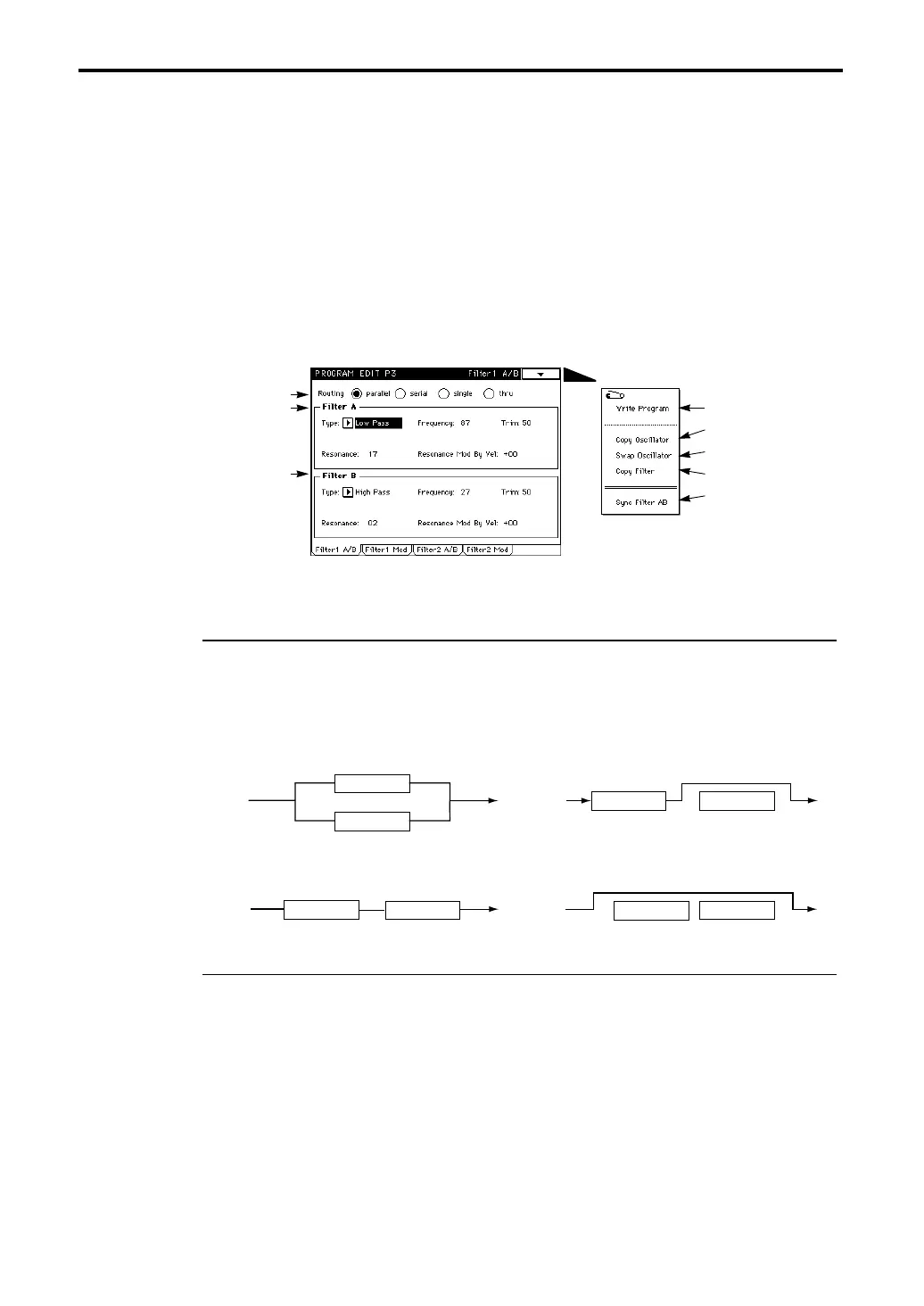
3–1a: Routing (Filter Routing) [parallel/serial/single/thru]
Specifies how filters 1A and 1B will be connected (refer to the diagram below).
If you wish to use Band Pass filters to create two peaks, select parallel.
If you wish to use Band Reject filters to create two valleys, select serial. In this case, setting filters
1A and 1B to the same settings will cause the cutoff slope to be more narrow.
If you wish to use only filter 1A, select single.
3–1b: Filter 1A
Makes basic settings for filter 1A.
Type (Filter Type) [Low Pass, High Pass, Band Pass, Band Reject]
Selects the filter type.
Frequency (Cutoff Frequency) [0…99]
Sets the cutoff frequency.
3–1a
3–1b
3–1c
Page Menu
3–1A
3–1B
3–1C
3–1D
3–1E
Filter 1A Filter 1B
thru
Filter 1A
Filter 1B
parallel
Filter 1A Filter 1B
serial
Filter 1A
Filter 1B
single