3–1: Filter 1 A/B (Filter 1A/Filter 1B)
26
3–1c: Filter 1B
These parameters will be displayed if “1–1c: Oscillator mode” is set to double, and “3–1a: Rout-
ing” is set to parallel or serial.
For details refer to “3–1b: Filter 1A.”
▼ Page Menu Command
3–1A: Write Program
This command writes an edited program into the specified program number of the specified bank.
Be sure to write important programs. If you turn the power off or select a different program before
writing, the data cannot be recovered.
For details refer to Basic Guide page 23, “9. Writing a program or combination.”
3–1B: Copy Oscillator
This command copies the settings of oscillator 1 or 2 from the specified program to the oscillator of
the program being edited. You may also select a program from another bank as the copy source.
When copying Oscillator 2 to Oscillator 1, if Filter 1 EG, Amp 1 EG, Oscillator 1 LFO, or Filter 1
LFO is selected for Oscillator 2 AMS, the settings will be automatically converted from Filter 1
EG to Filter EG, from Amp 1 EG to Amp EG, from OSC 1 LFO to OSC LFO, and from Filter 1
LFO to Filter LFO.
3–1C: Swap Oscillator
This command exchanges the settings of oscillator 1 and 2 within the program being edited.
If an Oscillator 2 with AMS settings of Filter 1 EG, Amp 1 EG, Oscillator 1 LFO, or Filter 1 LFO
is used for Oscillator 1 as a result of a Swap Oscillator command, the settings will be automat-
ically converted from Filter 1 EG to Filter EG, from Amp 1 EG to Amp EG, from OSC 1 LFO to
OSC LFO, and from Filter 1 LFO to Filter LFO.
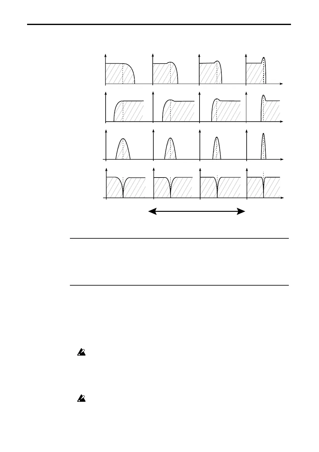
The result of applying Resonance
Low Pass
Level
Level
Level
Level
High Pass
Band Pass
Band Reject
Low Resonance setting
High Resonance setting