BA 348-01 * 2.0 * 34801b110.fm 1-19
Introduction 1
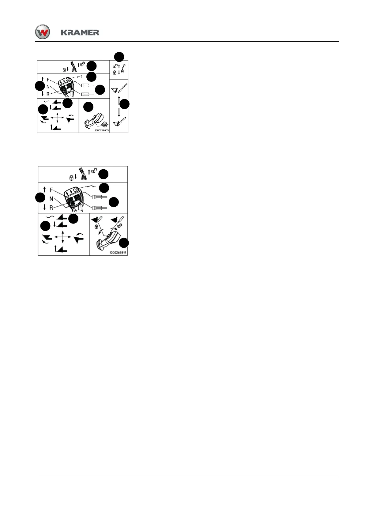
Label for control lever operation of 3rd control circuit, mechanical locking
• A = travel direction: (F) forward/(R) reverse and (N) neutral position
• B = mechanical locking/unlocking of control lever (joystick)
• C = mechanical locking/unlocking of control lever (3rd control circuit for attachments)
• D = front socket (brief operation) (option)
• E = coupling plug of additional hydraulic control circuit (option)
• F = operation: raise, lower, tilt in/out loader unit
• G = operation: loader unit float position (option)
• H = operation: differential lock (option)
• I = operation: 3rd control circuit: unlocking and locking the attachments on the quickhitch
and hydraulic control circuit for attachments
Location
On rear side of loader unit bulkhead
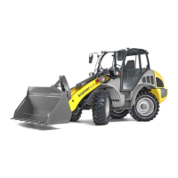
Label for control lever operation and 3rd control circuit (option), electrical locking
• A = travel direction: (F) forward/(R) reverse and (N) neutral position
• B = mechanical locking/unlocking of control lever (joystick)
• C = front socket (brief operation) (option)
• D = coupling plug of additional hydraulic control circuit (option)
• E = operation: raise, lower, tilt in/out loader unit
• F = operation: loader unit float position (option)
• G = operation: 3rd control circuit: unlocking and locking the attachments on the quickhitch
and hydraulic control circuit for attachments
Location
On rear side of loader unit bulkhead
Fig. 19 : Label: control lever operation
A
D
B
E
F
I
C
G
H
Fig. 20 : Label: control lever operation
A
C
B
D
F
E
F