6 Initial Operation
6.2 Adapting coupling points
38
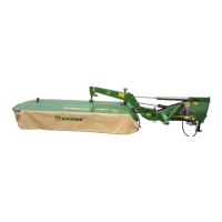
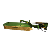
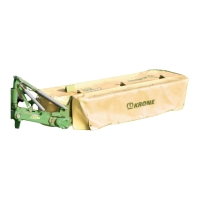
ActiveMow R 200
Original Operating Instructions 150000521_04_en
KM000-410
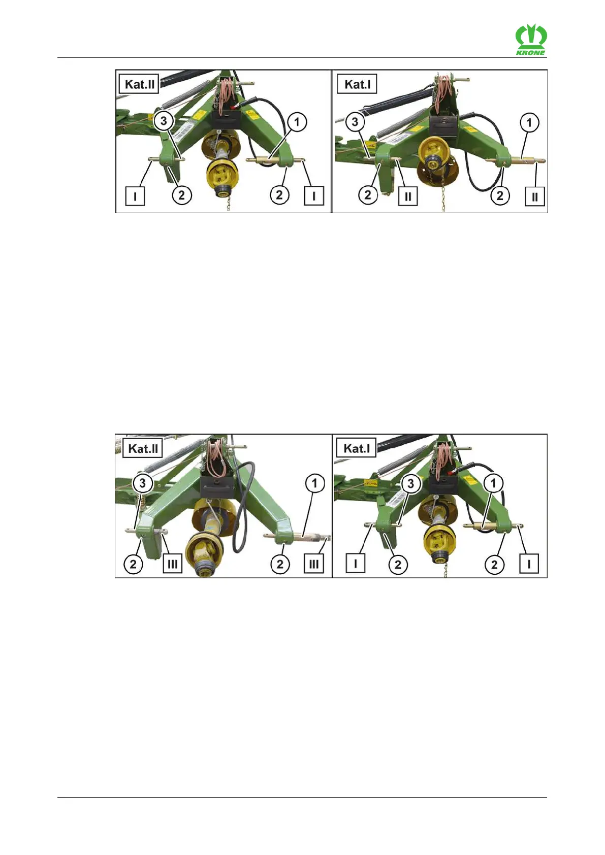
There are two possibilities to mount the mower:
Ball sleeves of category II (cat. II)
The lower link pins are mounted in the factory for category II (cat. II) in the position I (I).
Ball sleeves of category I (cat. I)
For ball sleeves of category I (cat. I), the lower link pin (1) must be offset outwards.
Unscrew the cylinder screws (2).
Pull out the shorter lower link pin (3), turn it by 180° and insert it from the inside.
Pull out the longer lower link pin (1) outwards up to the next borehole.
Secure both lower link pins (1, 3) with the cylinder screws (2).
KM000-433
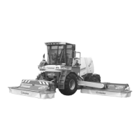
On wider tractors or when working in combination with front mounted mower (working width of
approx. 2.8–3.2m), it is recommended to reconnect the lower link pins (1,3) for the ball sleeves
of category II (cat. II) into position (III). For the ball sleeves of category I (cat. I) it is
recommended to reconnect the lower link pins (1,3) into position (I)
Ball sleeves of category II (cat. II)
Unscrew the cylinder screws (2).
Pull out the shorter lower link pin (3), turn it by 180° and insert it from the inside.
Pull out the longer lower link pin (1) outwards up to the next borehole.
Secure both lower link pins (1,3) with the cylinder screws (2).
 Loading...