Hardware
6of 70
Hardware R2.2.8 1 1.98.02 en
1.2 Structure
The controller contains all the components and functions which are required to operate the
robot. It comprises the processor and power units, which are both installed in a common con-
trol cabinet.
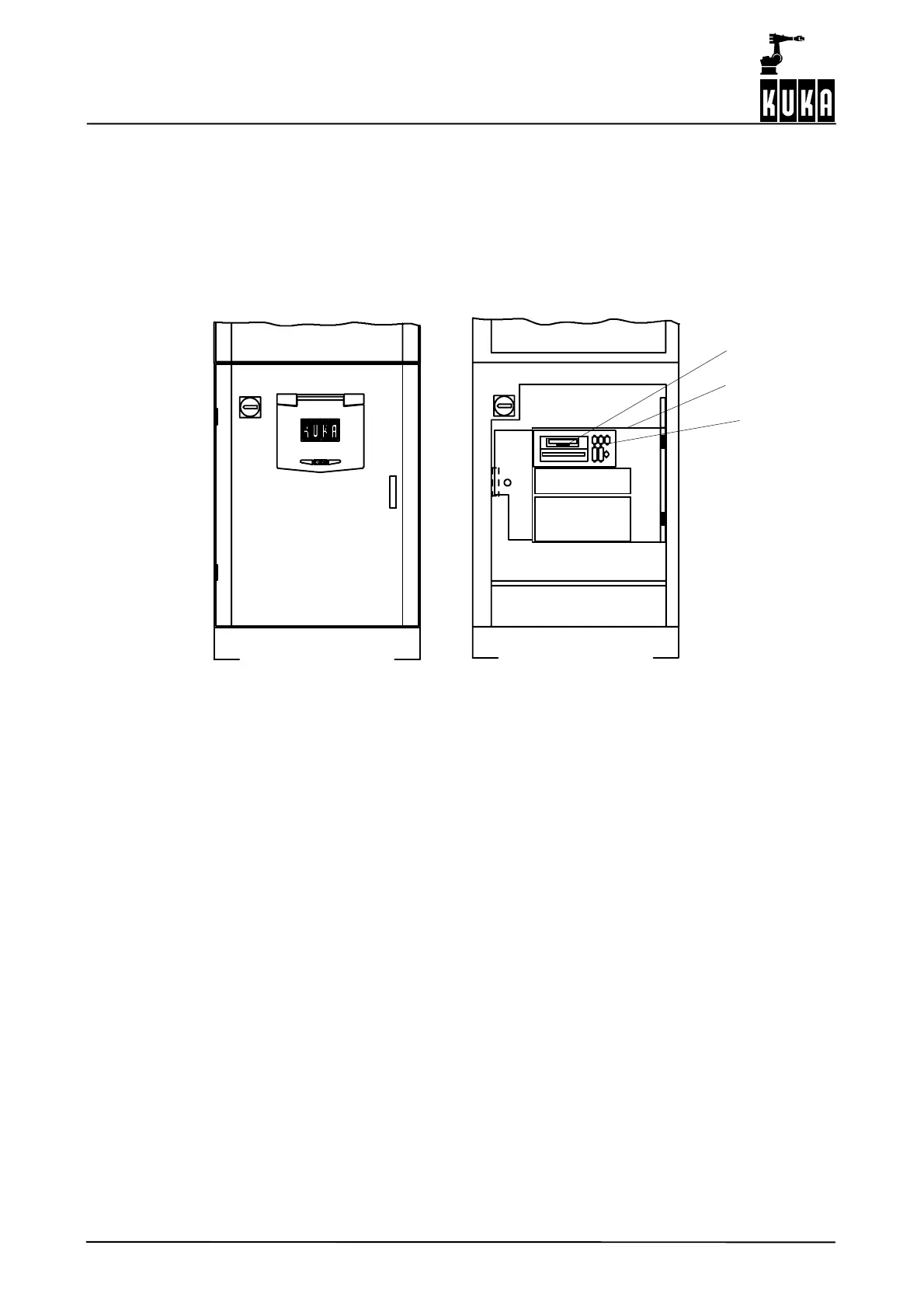
1.2.1 Processor unit
The processor unit includes the modules highlighted in Fig. 1.
Q1
A1
CD and floppy drives
Swing frame
Interfaces
Fig. 1 Processor unit
With its fitted components, the processor unit performs all the functions of the control
hardware. These are:
-- Windows user interface with visual display and input
-- Progr am cr e at ion, co r r e ct io n , a r c h ivi n g, and maint enan c e
-- Diagnosis, start--up assistance
-- Sequence control
-- Trajectory planning
-- Control of the servo power unit
-- Monitoring functions
-- Part s of the saf et y logic
-- Communication with external units (other controllers, host computers, PCs, network)
The control hardware is composed of the following modules:
-- Standard PC hardware with Pentium processor
-- Multi--function card (MFC)
-- Digital servo--electronics (DSEAT)
-- Resolv er / d i g it al conv e r t er (RDC ) on the robot