65 / 109Issued: 11.10.2013 Version: KST VisionTech 2.1 V1
10 Configuration
model points are listed in the table. For each model point, the model type is
specified and whether or not it has been found. The maximum and mean error
when finding the model point are also specified. For good results, the RMS er-
ror should be < 1 mm.
10.11 Testing a 3D task
Precondition The task has been configured.
The model has been generated.
The base is the same as was used for model generation.
The NULLFRAME tool is selected.
Procedure 1. In the main menu, select VisionTech > Task configuration.
2. Move the robot to the reference pose.
3. In the Task area, press Test.
The test is carried out and a result window is displayed.
4. The images in the result window can be enlarged. To do so, press the de-
sired image once.
If user data from the tool block have been transferred, they are displayed
beneath the enlarged image.
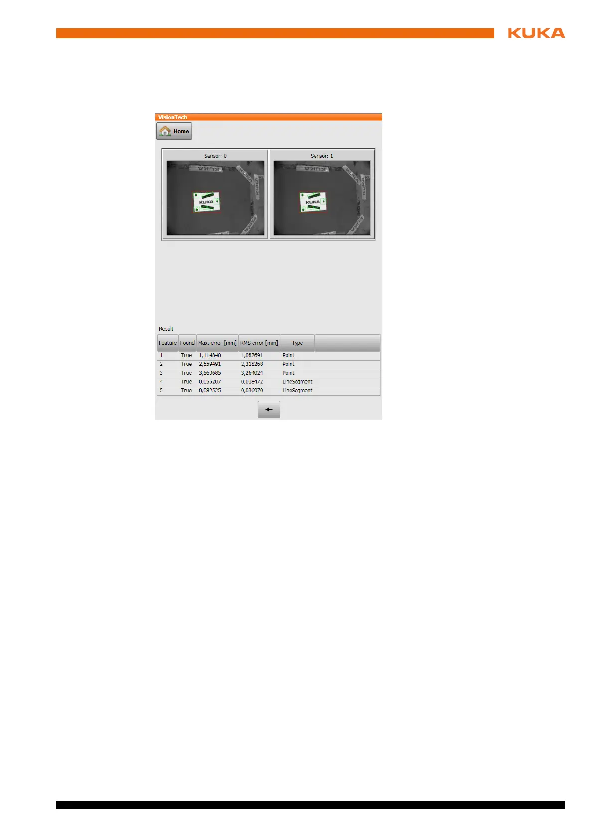
Description Once the test has been performed, a result window with images and a table is
displayed.
Areas detected by the cameras are indicated in green in the images. Areas
that have not been detected are marked in red. The differences between the
reference position and the calculated position are displayed in the table. If mul-
tiple components have been detected, the tables are displayed on tabs.
Fig. 10-7: Result of 3D model generation (example)