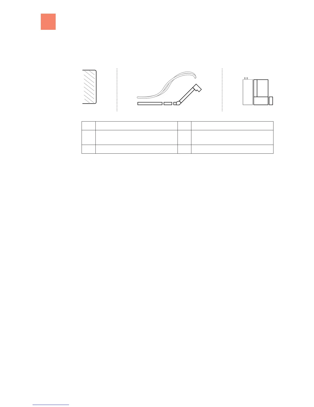
Schematic diagram of the system elements
1 Fuel storage room 4 Burner with heat exchanger and control
2 Conveyor system:
Suction conveyor system and/or worm
5 Ash container
3 Hopper (optional)
Safety elements
We have taken the following measures in order to maximize the safety of our systems.
Cellular wheel sluice
The cellular wheel sluice, developed by KWB as backfire-protection device ( according to
TRVB H118), prevents fire from being able to spread back to the fuel feed from the combustion
chamber.
Negative pressure monitoring
The continuous monitoring and control ensures the negative pressure in the combustion cham-
ber.
Photocell monitoring
Direct photocell monitoring of the combustion chamber allows the control to be able to react
significantly faster because it does not have to wait for a temperature change at a measure-
ment point.
Safety thermostat
This system switches off the heating system if the boiler temperature should increase to 95 C.
Sensor for flue gas temperature
In conjunction with the photocell, the sensor for flue gas temperature monitors the fill level and
the ignition procedure in the combustion chamber.
Photocell
In conjunction with the sensor for flue gas temperature, the photocell monitors the fill level and
the ignition procedure in the combustion chamber.
Lambda control system
The lambda control system adapts the combustion to various fuel qualities.
2
2.1
2.2
2
Overview
10
B KWB Easyfire EN, 05.2011