2A3/4
2-3-3
long paper.
11.Upper lift limit switch (LICSW-U) .................Detects the upper drawer lift reaching
the upper limit.
12.Lower lift limit switch (LICSW-L) ..................Detects the lower drawer lift reaching
the upper limit.
13.Paper feed switch 1 (PFSW1) .....................Controls feed clutch 4.
14.Paper feed switch 2 (PFSW2) .....................Controls feed clutch 1, 2 and 3, and the
upper paper feed clutch.
15.Paper feed switch 3 (PFSW3) .....................Controls the lower paper feed clutch.
16.Paper feed switch 4 (PFSW4) .....................Controls feed clutch 3.
17.Feed switch (FSW) ......................................Controls the secondary paper feed start
timing.
18.Registration switch (RSW) ...........................Controls the secondary paper feed end
timing.
19.Eject switch (ESW) ......................................Detects paper jam in the fixing section.
* For inch specifications only.
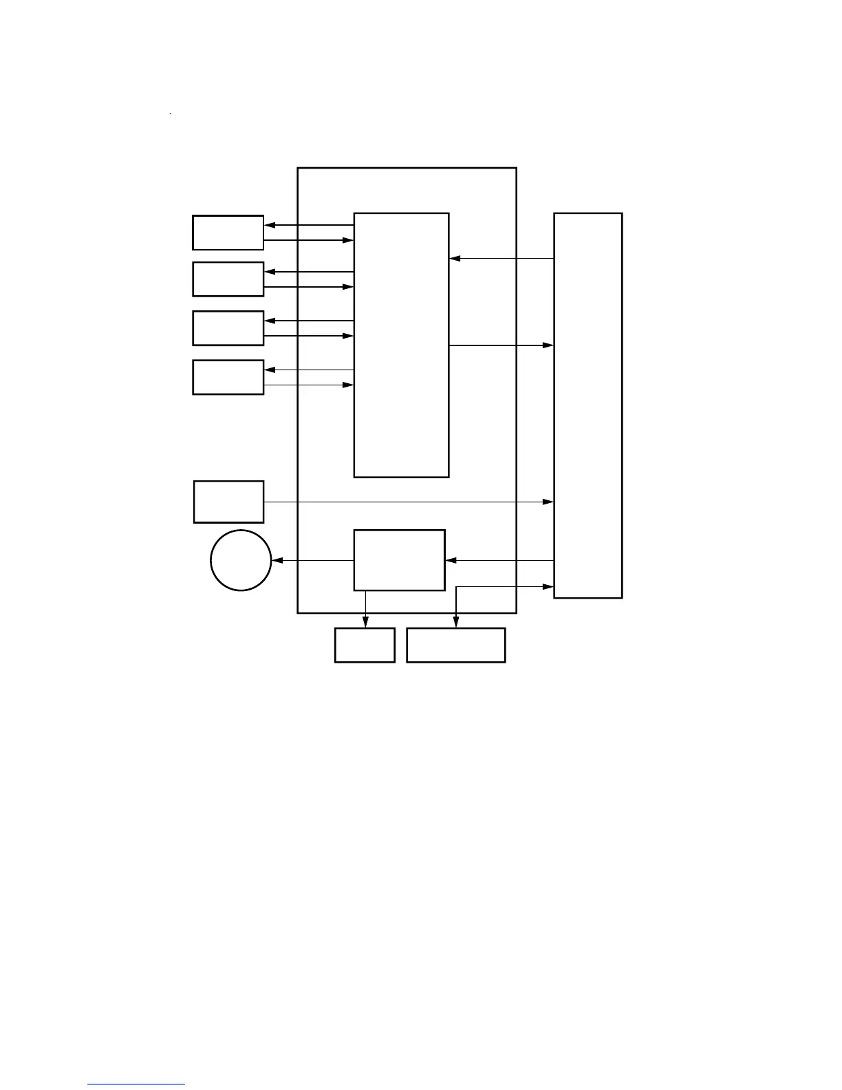
2-3-2 Engine PCB
Figure 2-3-2 Engine PCB block diagram
The engine PCB (EPCB) transmits the status of each switch to the main PCB (MPCB)
and transmits the control signals output from the main PCB (MPCB) through driver ICs
to motors, clutches and solenoids. It also receives and transmits input and output
signals to and from optional devices via a communication interface.
EPCB
Communication
interface
Driver
IC
Main PCB
Finisher*
3
Motors
High-voltage
transformer PCB
Switches,
sensors
Clutches,
solenoids
Large paper
deck*
2
MMD*
4
*3: Optional.
*4: Optional for 120 V specifications only.
*1: Optional for 42 ppm only.
*2: 42 ppm: Optional/52 ppm: standard
Paper feed
desk*
1

 Loading...


