2A3/4
3-6-81
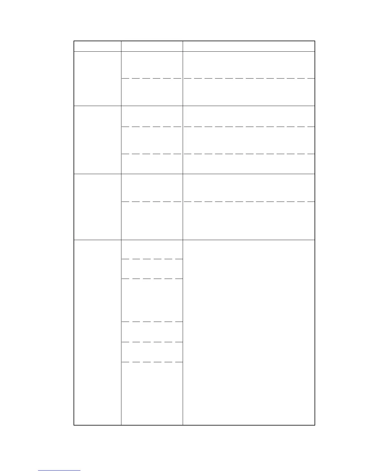
Defective inverter
PCB.
Defective scanner
motor PCB.
Broken wire in fix-
ing heater M or S.
Fixing unit
thermostat trig-
gered.
Broken fixing unit
thermistor wire.
Dirty sensor part of
the fixing unit ther-
mistor.
Defective engine
PCB.
Broken main
charger wire.
Leaking main
charger housing.
Poor contact in the
high-voltage
transformer PCB
connector
terminals.
Defective main
PCB.
Defective engine
PCB.
Defective high-
voltage trans-
former PCB.
If the exposure lamp does not turn off with
CN1-5 and CN1-6 on the inverter PCB high,
replace the inverter PCB.
If CN3-1 and CN3-2 on the scanner motor
PCB are always low, replace the scanner
motor PCB.
Check for continuity across each heater. If
none, replace the heater (see page 3-3-63).
Check for continuity across thermostat. If
none, remove the cause and replace the
thermostat.
Measure the resistance. If it is ∞ Ω, replace
the fixing unit thermistor.
Check visually and clean the thermistor sen-
sor parts.
If fixing heater M/S stays on while CN6-7
and CN6-8 on the engine PCB go high,
replace the engine PCB.
See page 3-6-5.
Problem Causes Check procedures/corrective measures
(28)
The exposure
lamp does not
turn off.
(29)
Fixing heater
M or S does
not turn on
(C620).
(30)
Fixing heater
M or S does
not turn off
(fixing unit
thermostat
triggered;
C620).
(31)
Main charging
is not per-
formed
(C510).

 Loading...


