2FB/2FC
1-6-62
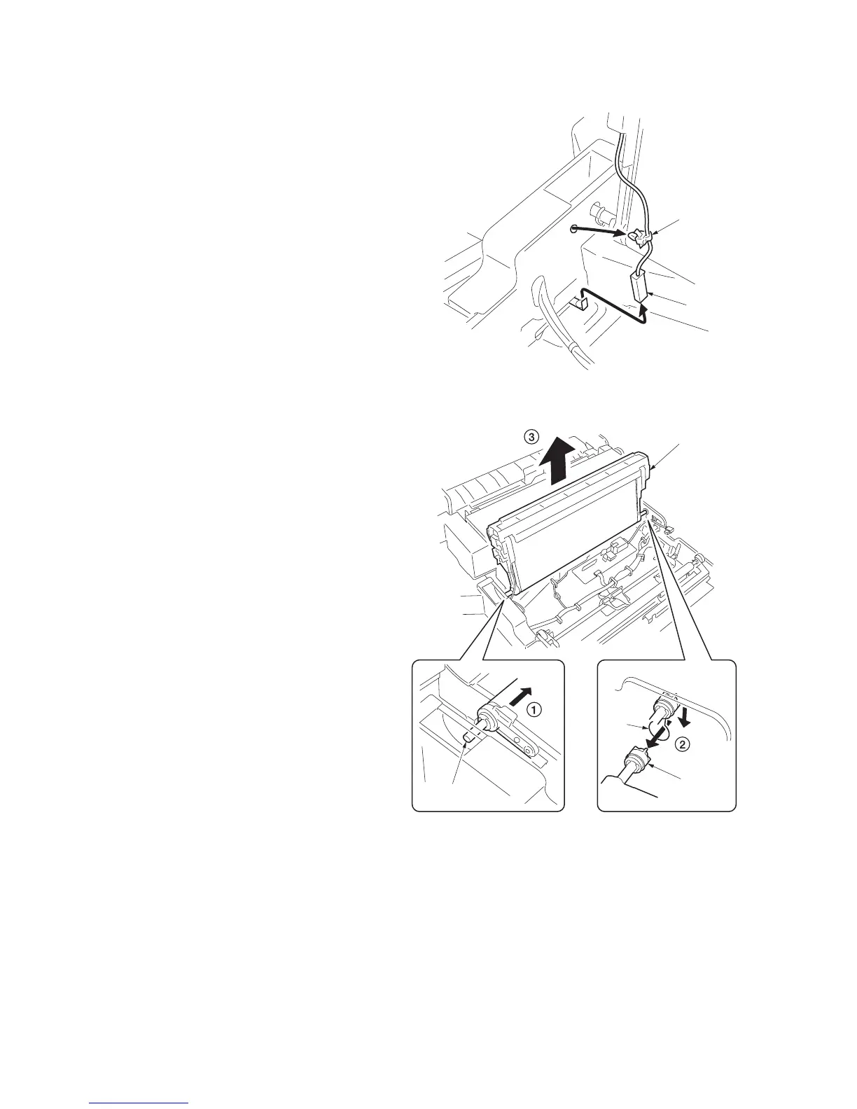
5. Remove the connector and band of the
paper conveying unit front.
Figure 1-6-115
6. After sliding the transfer unit to end and pull-
ing out the front shaft from the frame, pull
out the rear coupling from the hole of the
frame as shown in the figure, and remove
the transfer unit from the paper conveying
unit.
Figure 1-6-116
Connecto
 Loading...


