2FB/2FC-3
1-6-93
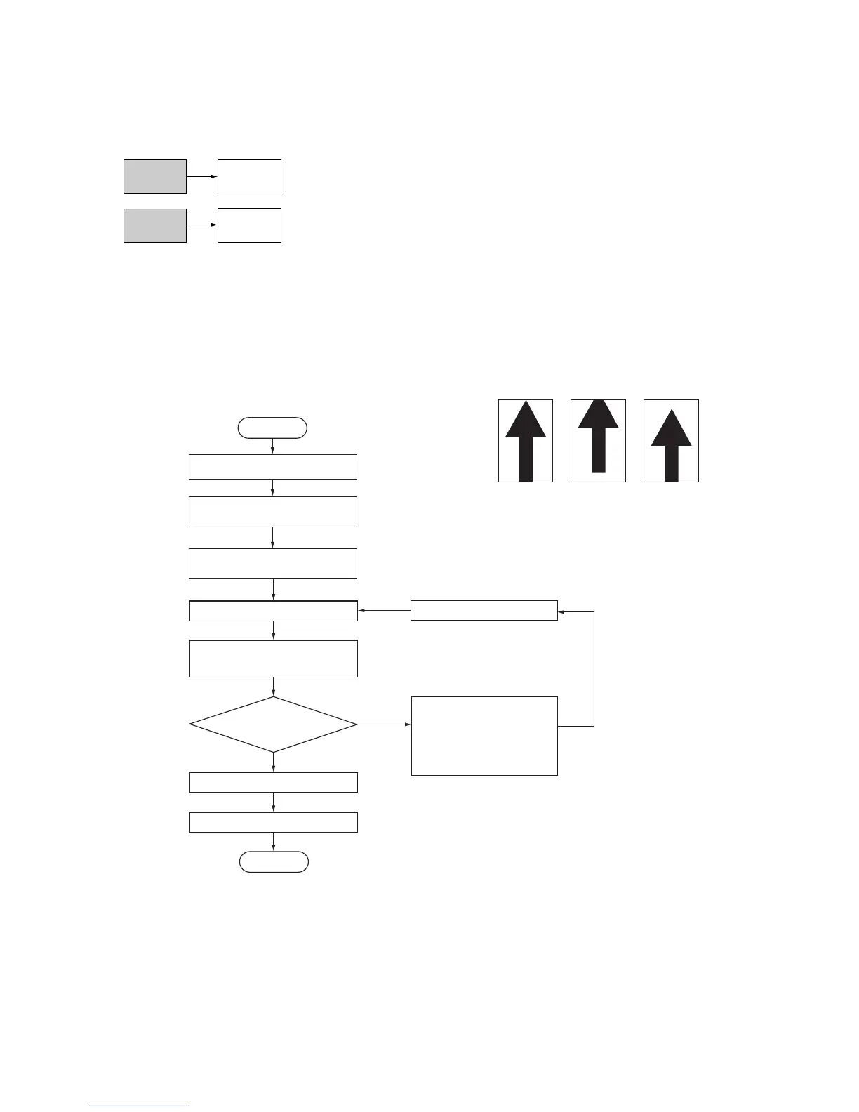
Yes
No
End
For copy example 1,
decrease the value using
the cursor down key.
For copy example 2,
increase the value using
the cursor up key.
Press the interrupt key.
Exit maintenance mode.
Press the stop/clear key.
Place an original on the document
processor and make a test copy.
Is the image correct?
Setting range (Initial setting)
CCD leading edge timing: -32 to +32 (0)
CIS leading edge timing: -32 to +32 (0)
CIS leading edge timing for rote copying:
-20 to +20 (0)
Changing the value by 1 moves
the copy image by 0.19 mm.
(ADJUST DATA1/ADJUST DATA3)
Changing the value by 1 moves
the copy image by 0.17 mm.
(ADJUST DATA5)
Decreasing the value moves the copy
image backward, and increasing it
moves the image forward.
After performing adjustment of U071 (ADJUST DATA3)
and U072 (ADJUST DATA2), adjust U071 (ADJUST DATA5)
and U072 (ADJUST DATA3).
Press the start key.
The new setting is stored.
Enter maintenance mode.
Start
Enter 071 using the numeric
keys and press the start key.
Select the item to be adjusted
on the touch panel.
Touch panel display
ADJUST DATA1: CCD leading edge timing
ADJUST DATA3: CIS leading edge timing
ADJUST DATA5: CIS leading edge timing
for rotate copying
(7) Adjusting the scanning start position when the DP is used
Perform the following adjustment if there is a regular error between the leading or trailing edges of the original and the
copy image.
<Caution>
Check the copy image after the adjustment. If the image is still incorrect, perform the above adjustments in maintenance
mode.
(7-1)Adjusting the leading edge registration
<Procedure>
Figure 1-6-182
U404
(P. 1-6-95)
U071
Front (CCD adjustment)
Back (CIS adjustment)
U404
(P. 1-6-95)
U071
Original
Copy
example 1
Copy
example 2
 Loading...


