2L6/2N6/2N5/2N4
1-4-316
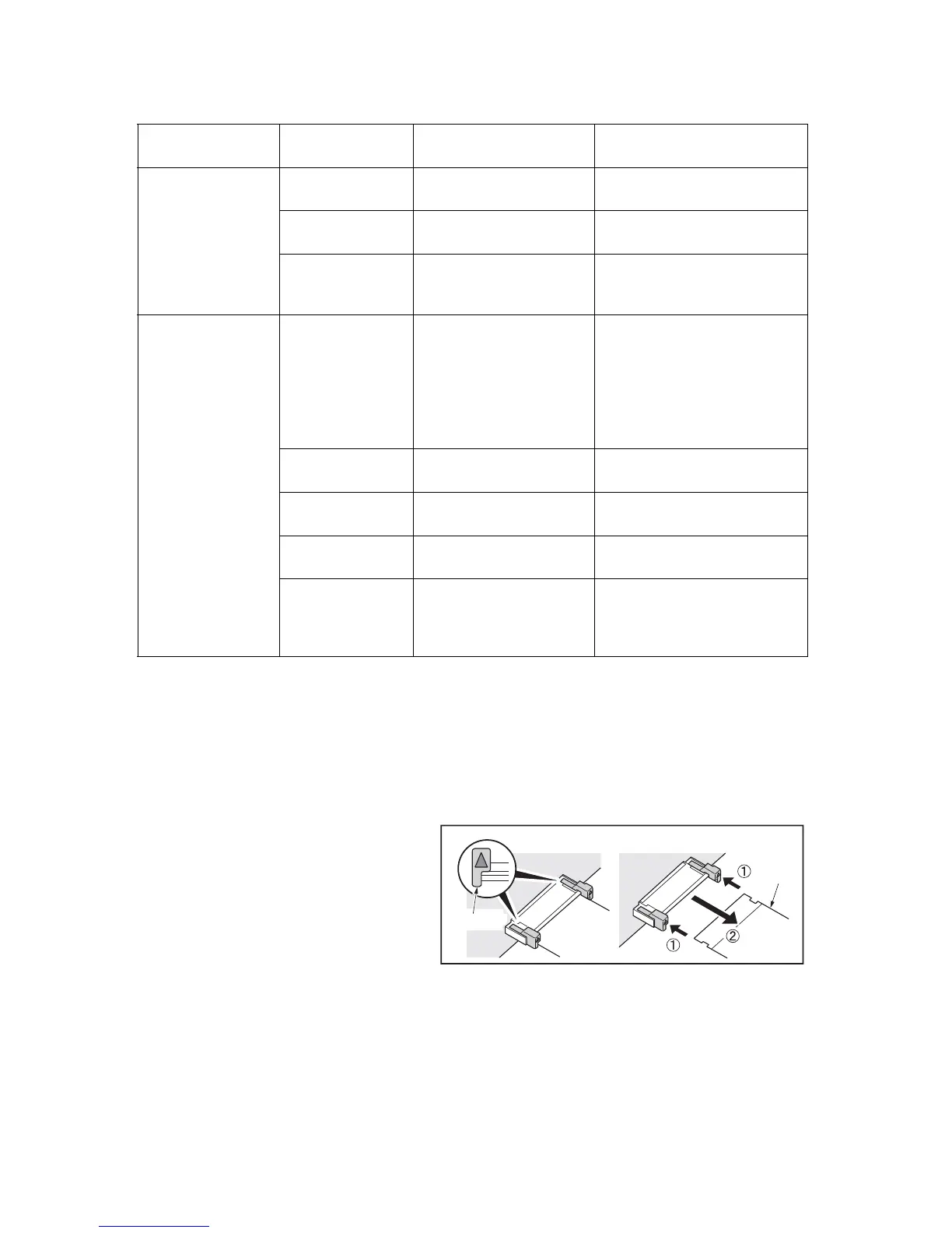
(2) Remarks on Relay PWB replacement
To remove the FFC from the locked connector, unlock the connector by pressing the lock lever at the triangu-
lar mark.
To insert an FFC cable, hold it at both ends and insert it all the way in.
Figure 1-4-8
11.Printing is not
possible with Com-
mand Work Station.
Defective bridge
board.
Bridge board mounting
error.
Replace the bridge board.
Defective main
board.
Main board mounting error. Replace the main board.
Defective Printing
system.
Board mounting failure in
the Printing system.
Replace the Printing system.
12.An abnormal
printing occurs when
printing from Com-
mand Work Station.
Connection error of
the harness
between the Main
board and the
Bridge board (dam-
aged or loose con-
nected).
Defective cable or poor
contact.
Reinsert the connector. Also
check for continuity within the
connector cable. If none, replace
the cable.
Defective bridge
board.
Bridge board mounting
error.
Replace the bridge board and
check for correct operation.
The image data is
not entered.
Engine board mounting
error.
Replace the engine board and
check for correct operation.
Defective main
board.
Main board mounting error.
Replace the main board and
check for correct operation.
Defective Printing
system.
Board mounting failure in
the Printing system.
Replace the Printing system and
check for correct operation.
Problem/
Error code
Condition of
detection
Causes
Check procedures/ Corrective
measures
 Loading...