Mechanical safety
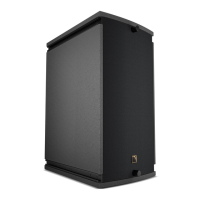
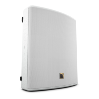
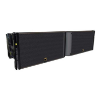
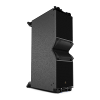
A15 Wide/Focus
conguration rigging accessory maximum / safe limit
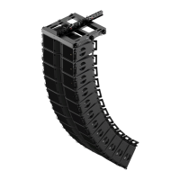
Stacked vertical array No rigging accessory 1
Stacked vertical array KS21-OUTRIG 4
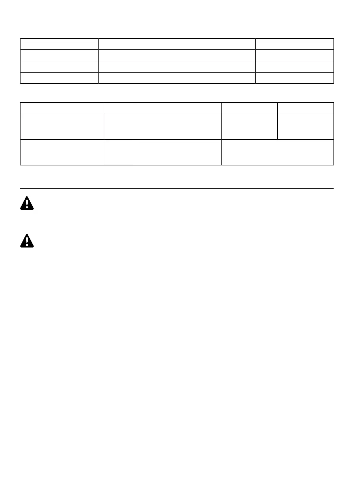
Pole-mounted A-MOUNT 1
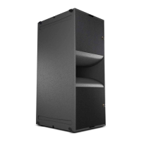
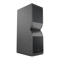
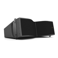
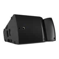
A15 Wide/Focus on KS21
conguration rigging accessory safe limit maximum limit
Stacked on subwoofer with
angle adjustment
A-TILT + KS21-OUTRIG
or KS21-CHARIOT with K2-JACK
4 (including KS21)
4 A15 Wide/Focus
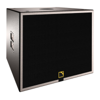
4 KS21
Stacked on subwoofer
KS21-OUTRIG
or KS21-CHARIOT with K2-JACK
3 A15 Focus / 2 A15 Wide
3 KS21
Assessing mechanical safety
Mechanical safety of the rigging system
Before any installation, always model the system in Soundvision and check the Mechanical Data section for
any stress warning or stability warning.
In order to assess the actual safety of any array conguration before implementation, refer to the following warnings:
Rated working load limit (WLL) is not enough
The rated WLL is an indication of the element resistance to tensile stress. For complex mechanical systems such as
loudspeaker arrays, WLLs cannot be used per se to determine the maximum number of enclosures within an array
or to assess the safety of a specic array conguration.
Maximum pullback angle
If a pullback accessory is available, the pullback angle must not exceed a 90° negative site angle.
Mechanical modeling with Soundvision
The working load applied to each linking point, along with the corresponding safety factor, will depend on
numerous variables linked to the composition of the array (type and number of enclosures, splay angles) and the
implementation of the ying or stacking structure (number and location of ying points, site angle). This cannot be
determined without the complex mechanical modeling and calculation offered by Soundvision.
Assessing the safety with Soundvision
The overall safety factor of a specic mechanical conguration always corresponds to the lowest safety factor
among all the linking points. Always model the system conguration with the Soundvision software and check the
Mechanical Data section to identify the weakest link and its corresponding working load. By default, a stress
warning will appear when the mechanical safety goes beyond the recommended safety level.
Safety of ground-stacked arrays in Soundvision
For ground-stacked arrays, a distinct stability warning is implemented in Soundvision. It indicates a tipping hazard
when the array is not secured to the ground, stage or platform. It is the user's responsibility to secure the array
and to ignore the warning.
Additional safety for own arrays
When ying an array, use available holes to implement a secondary safety.
Considerations must be given to unusual conditions
Soundvision calculations are based on usual environmental conditions. A higher safety factor is recommended
with factors such as extreme high or low temperatures, strong wind, prolonged exposition to salt water, etc.
Always consult a rigging specialist to adopt safety practices adapted to such a situation.
44 A15 owner's manual (EN) version 1.2
 Loading...