1.3.4 E xtension Cabl e 3
| www.lakeshore.com
1.3.4 Extension Cable
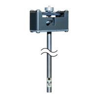
The complex nature of Hall effect measurements makes it necessary to match exten-
sion cables to the probe when longer cables are needed. Keeping probes and their
extensions from getting mixed up can become a problem when more than one probe
is used. The Model 425 alleviates most of the hassle by allowing you to match probes
to extension cables in the field. Stored information can be viewed on the front panel
and read over the computer interface to ensure proper mating.
1.3.5 Hall Effect
Generators (Magnetic
Field Sensors)
The Model 425 will operate with a discrete Hall effect generator when a suitable
probe is not available. You can program the nominal sensitivity and serial number
into an optional HMCBL blank connector to provide all gaussmeter functions except
field compensation. If no sensitivity information is available, the Model 425 reverts to
resistance measurement.
1.4 Display and
Interface Features
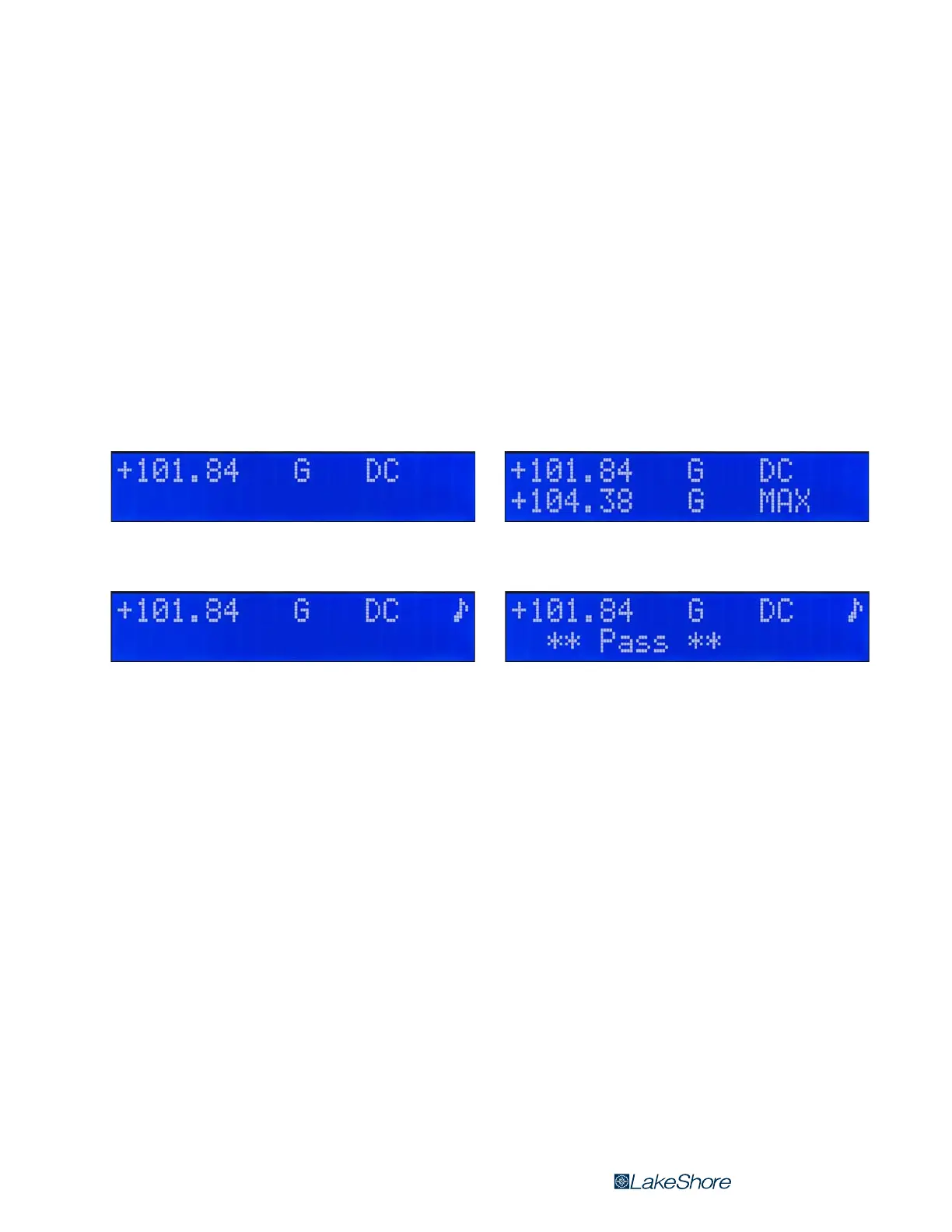
The Model 425 has a 2-line by 20-character liquid crystal display. During normal
operation, the display is used to report field readings and give results of other fea-
tures such as max or relative. When setting the instrument parameters, the display
gives you meaningful prompts and feedback to simplify operation.
Following are four examples of the various display configurations:
1.4.1 Keypad
The instrument keypad has 14 keys with individual keys assigned to frequently used
features. Menus are reserved for less frequently used setup operations. The keypad
can be locked out to prevent unintended changes of instrument setup.
1.4.2 Alarm, Relay and
Sort
High and low alarm functions and one relay are included with the instrument, and
can be used to automate repetitive magnet testing and sorting operations. Alarm
actuators include display annunciator, audible beeper, and a relay. The alarm can be
configured to display a pass or fail message and the relay can be configured to acti-
vate a mechanism to separate parts that meet pre-set fail criteria. The relay can also
be controlled manually for other system needs.
1.4.3 Monitor Output
The monitor output provides an analog representation of the reading that is cor-
rected for probe offset and nominal sensitivity. This feature makes it possible to view
the analog signal, which has not been digitally processed. The monitor output can be
connected to an oscilloscope or data acquisition system.
FIGURE 1-2 Left: Normal reading—the default mode with the display of the live DC field reading;
Right: Max DC hold on—the maximum value is shown in the lower display while the upper display contains the live DC field reading;
FIGURE 1-3 Left: Alarm on—the alarm gives an audible and visual indication of when the field value is selectively outside or inside a user
specified range; The relay can be associated with the alarm;
Right: Sort on—the live reading is shown in the upper display while the lower display contains the pass/fail (repetitive sorting or testing)
message. The relay facilitates pass/fail operation


 To Next Page