4.3.1 Di splay Unit s 31
| www.lakeshore.com
4.3.1 Display Units
4.3.2 Display
Annunciators
There are display annunciators that appear as necessary to indicate additional infor-
mation. Display annunciators are visible when their associated feature is enabled.
4.4 Display Setup
This section describes how to set up the field units and display contrast.
4.4.1 Field Units
Parameter
The field units parameter determines which units are used to display the measured
field, maximum field, and relative field readings.
Menu navigation:
Units (gauss, tesla, oersted, or ampere/meter)
Default: gauss
Interface command: UNIT
4.4.2 Display Contrast
The front panel LCD display contrast can be adjusted for optimal viewing. The default
should work well in most standard room temperature environments, but deviations
from room temperature and extreme viewing angles can cause the display contrast
to require adjustment for optimal viewing.
Menu navigation:
Interface (press and hold for 3 s)Q ContrastQ (1 to 32)
Default: 10
Interface command: BRIGT
4.5 DC and RMS
Measurement
Modes
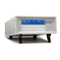
The Model 425 can be configured for DC or RMS measurements. Pressing
DC/RMS toggles between DC and RMS measurement modes. The DC/RMS annuncia-
tor on the display will immediately change to DC or RMS, depending on what mea-
surement mode has been selected.
Unit Description
G Field in gauss
T Field in tesla
Oe Field in oersted
A/m Field in ampere/meter
¦ Resistance in ohms
TABLE 4-2 Display units
Annunciator Function
DC, RMS DC or RMS mode readings
MX Indicates the max hold value; it is displayed on the lower row
° Indicates the relative reading; it is displayed on the upper row
SP Indicates the relative setpoint value
ª On steady when the alarm function is on; blinks when in the alarming state
** Pass **
Fail High
Fail Low
Shown when the sort parameter is enabled; indicates when a
measurement passes or fails the user-specified magnet test
TABLE 4-3 Display annunciators