5.2.7 Alarm and Relay Examples 39
| www.lakeshore.com
The relay has two modes of operation:
D Manual: allows you to turn the relay off (normal) or on (active) manually from the
front panel or over the computer interface.
D Alarm: the relay follows the operation of the alarms. You can tie the action of the
relay to the high alarm, low alarm, or both alarms. The relay is activated any time
the associated alarm is in an alarming state.
Menu navigation:
Alarm/Relay QalarmQlow alarm settingQ high alarm settingQ relay (on, off, alarm)
Default: off
Interface command: RELAY
If the relay is in alarm mode, you can associate the relay with the high, low or both
alarms. For example, if you associate the relay with the low alarm, the relay will only
be activated when the low alarm setpoint is breached. If it is set to “both”, the relay
will activate if either the high alarm or the low alarm setpoint is breached.
Menu navigation:
Alarm/Relay Q alarm Qlow alarm settingQ high alarm settingQ relay (alarm)Q
(low, high, both)
Interface command: RELAY
5.2.7 Alarm and Relay
Examples
Section 5.2.7.1 and section 5.2.7.2 describe some common applications where the
alarm function can be used. Although the alarm can be used in a variety of applica-
tions, these examples provide an overview of how the alarm features can be used
together.
5.2.7.1 Testing and Sorting of Discrete Magnets
A common application in magnet manufacturing is testing magnets after they have
been magnetized. In this example, the unmagnetized material comes down the
assembly line and enters the magnetizer. After it is magnetized, it continues to a QC
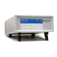
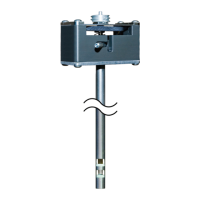
area where it is tested for field strength. An operator places the magnet into a fixture
where the Model 425 is used to measure the flux density. The magnet can be placed in
the fixture with the north pole facing either up or down.
In this application, the alarm should be setup with the magnitude setting since the
orientation is not a factor. The inside setting will be used with the audible setting on
so that the instrument sounds when the measured field is within tolerance. This will
give the operator an audible signal that the magnet passed the test. In this example,
the alarm sort parameter is chosen to also show a pass or fail condition on the
Model 425 display. The low alarm setpoint will be set to 0.9 kG (0.09 T) and the high
alarm setpoint will be set to 1.1 kG (0.11 T). The beeper will sound and the display will
indicate a ***Pass*** condition if the magnet has a field magnitude between the two
setpoints regardless of field polarity. If the field magnitude is less than 0.9 kG the dis-
play will indicate Fail Low, and if it is greater than 1.1 kG it will indicate Fail High.
Since the alarm is configured with the magnitude setting, a reading between -0.9 kG
and -1.1 kG will also indicate a ***Pass*** condition since the orientation is not a fac-
tor in this scenario.