40 cHAPTER 5: Advanced Operation
Model 425 Gaussmeter
5.2.7.2 Testing a Magnet Installed in an Assembly
Another common application is testing magnets installed into an assembly. In this
case, the orientation of the magnet matters. An example of this is the magnets used in
a motor assembly. In this instance, finished magnets are installed into a motor
assembly, and then they are verified using the Model 425 to measure the field magni-
tude and field polarity.
In this example, the alarm function will be setup the same as the previous example
with the exception of using the algebraic setting instead of the magnitude setting.
The algebraic setting is chosen since the orientation matters in this application. The
low setpoint will be set to 0.9 kG, and the high setpoint will be set to 1.1 kG. After the
assembly is placed on the test fixture, if the measured field is between the high and
low alarm setpoints, the part is considered conforming, and the display will indicate a
***Pass*** condition. If the measured field is -1.0 kG, the assembly is non-conforming
and the display will indicate Fail Low. In this case, the magnitude of the field was cor-
rect, but the magnet was installed with the wrong orientation.
5.2.7.3 Monitoring a Static Field
In this application, an electromagnet is used to generate a static field for an experi-
ment. This field is monitored using the Model 425. The results of the experiment are
valid only if the field remains stable within ±0.05 kG. If the field deviates beyond this
amount, the Model 425 will alarm indicating that the experimental results are no
longer valid. The relay will signal external equipment to shut down the experiment.
In this example, the alarm will be setup using the algebraic setting and the outside
setting. The experiment will be done at a field of 1 kG. The low alarm setpoint will be
set to 0.95 kG and the high alarm setpoint will be set to 1.05 kG. The relay will be
setup to follow both alarms. If the field remains between the two setpoints, the
instrument is not in an alarming state and the relay remains deactivated. If the field
goes higher than 1.05 kG or lower than 0.95 kG, then the instrument will alarm and
the relay will activate and shut down the experiment.
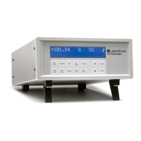
FIGURE 5-1 Alarm on with magnitude and outside settings
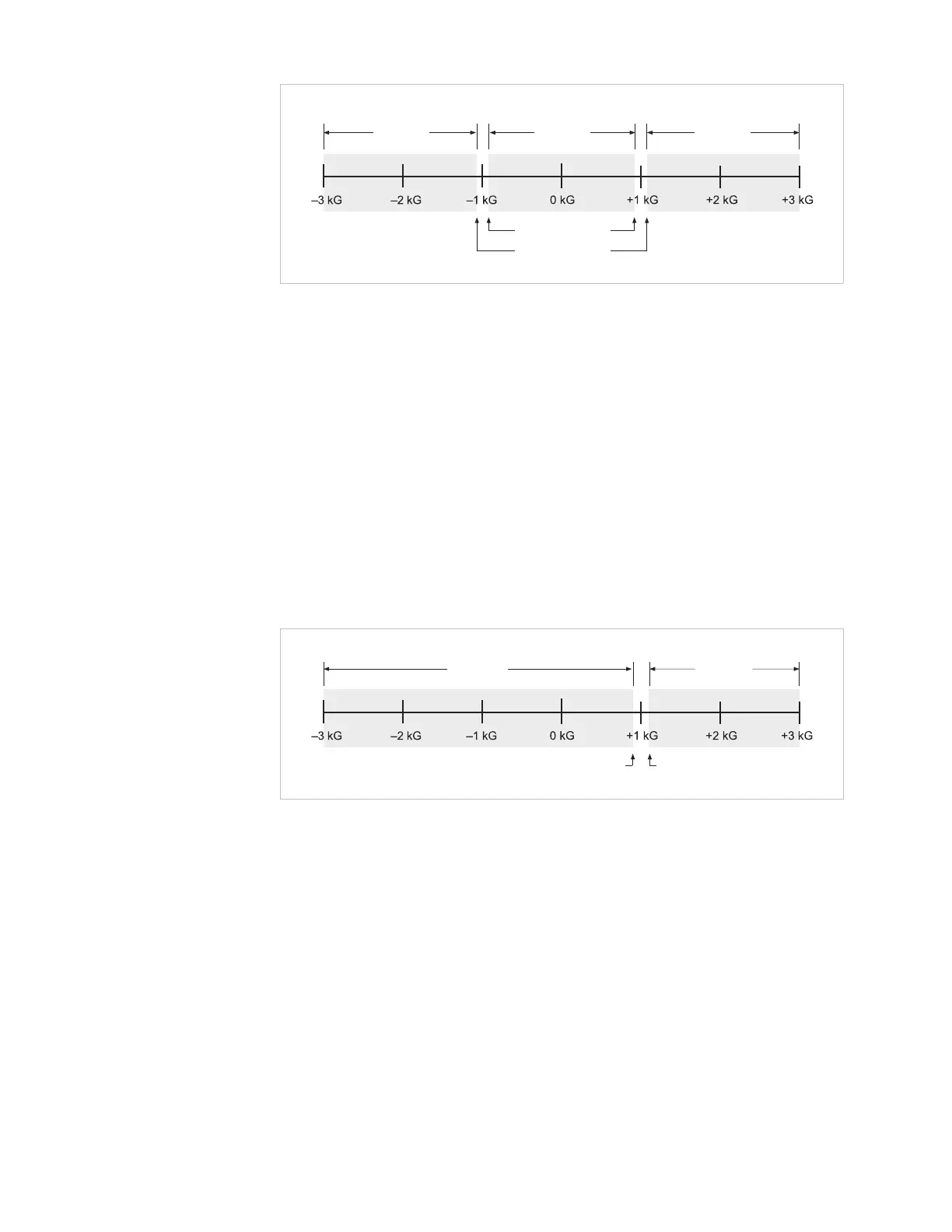
FIGURE 5-2 Alarm on with algebraic and outside settings
Pass
(alarming)
Pass
(alarming)
Fail low
(non-alarming)
Alarm triggered by readings
OUTSIDE user defined
setpoints in magnitude mode
Low alarm point
High alarm point
Fail high
(non-alarming)
Fail high
(non-alarming)
Alarm triggered by readings OUTSIDE
user defined setpoints in algebraic mode
Fail low
(non-alarming)
Fail high
(non-alarming)
Pass
(alarming)
Low alarm
point
High alarm
point