3.4.3 Power Switch 23
| www.lakeshore.com
3.4.3 Power Switch
The power switch is part of the line input assembly on the rear panel of the
Model 425, and it turns line power to the instrument on and off. When the circle is
depressed, power is off. When the line is depressed, power is on (FIGURE 3-2).
Position the instrument so that the power switch is easily accessible.
3.5 Probe Input
Connection
This section describes the probe input connection and pin-out details.
The Lake Shore Hall probe plugs into the 15-pin D-sub socket on the rear panel. Align
the probe connector with the probe input socket and push straight in to avoid bend-
ing the pins. For best results, secure the connector to the rear panel using the two
thumbscrews. A tight connector keeps the cable secure and prevents interference.
Refer to section 3.6 for additional probe considerations.
An electrically erasable programmable read only memory (EEPROM) is included in
each probe. The EEPROM stores specific information that the gaussmeter requires for
operation. The information includes serial number, probe sensitivity, field compensa-
tion data, and calibration data. When a new probe is connected, the instrument reads
parameters from probe memory and the probe is ready to use. A new probe can be
connected at any time even while the instrument is turned on. No parameters need to
be entered into the Model 425 for a Lake Shore probe. However, the zero probe func-
tion should be performed the first time a probe is used with the instrument and peri-
odically during use (section 4.5.1.2).
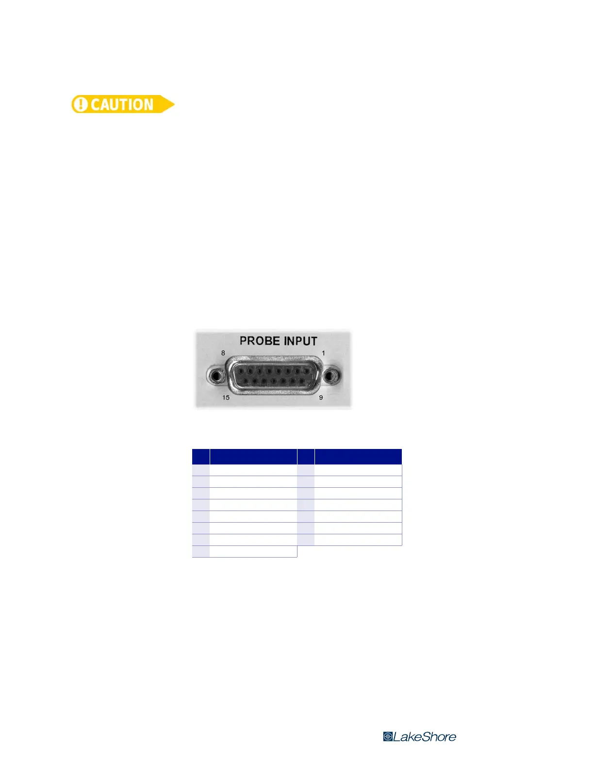
FIGURE 3-3 Probe input socket
Pin Description Pin Description
1V input +9V input –
2 Internal use only 10 No connection
3 Internal use only 11 EEPROM GND
4 Internal use only 12 EEPROM VCC
5 Internal use only 13 EEPROM CLK
6 Internal use only 14 EEPROM DATA
7 No connection 15 I Hall –
8 I Hall +
TABLE 3-2 Probe input connector details
 Loading...