22 cHAPTER 3: Installation
Model 425 Gaussmeter
3.4 Line Input
Assembly
This section describes how to properly connect the Model 425 to line power. Please
follow these instructions carefully to ensure proper operation of the instrument and
the safety of operators.
3.4.1 Line Voltage
The Model 425 will operate between the range of 100 VAC to 240 VAC, with 50 Hz or
60 Hz configurations so that it can be operated from line power anywhere in the
world. No user configuration is required for different voltage operations.
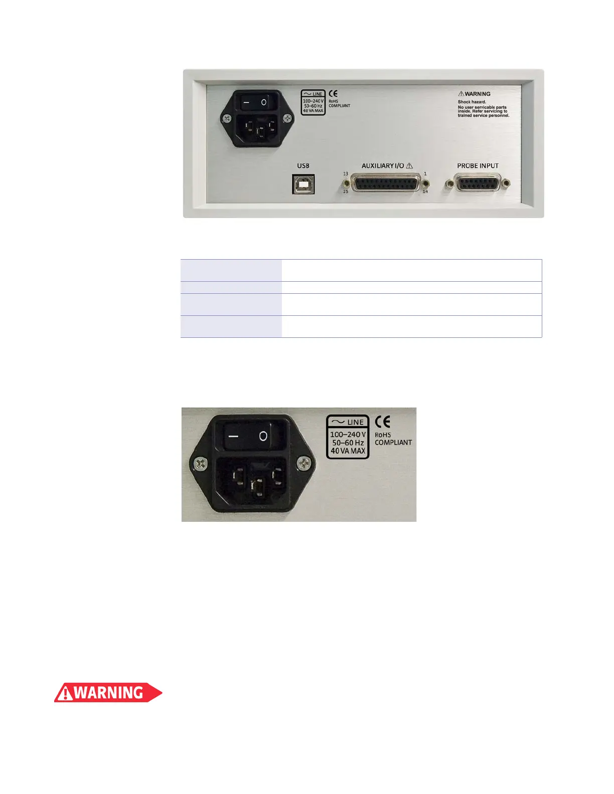
3.4.2 Power Cord
The Model 425 includes a 3-conductor power cord that mates with the IEC 320-C14
line cord receptacle. Line voltage is present on the two outside conductors, and the
center conductor is a safety ground. The safety ground attaches to the instrument
chassis and protects the user in case of a component failure. A CE approved power
cord is included with instruments shipped to Europe; a U.S. power cord is included
with all other instruments (unless otherwise specified when ordered).
Always plug the power cord into a properly grounded receptacle to ensure safe operation
of the instrument.
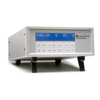
FIGURE 3-1 Model 425 rear panel
Line input assembly
Includes the IEC 320-C14 line cord receptacle and instrument power switch.
Refer to section 3.4.
USB interface Standard B-type USB connector. Refer to section 6.2 and see FIGURE 8-3.
Auxiliary I/O
25-pin D-sub that provides access to the monitor output and relays.
Refer to section 3.7.
Probe input
15-pin D-sub for probes or Hall generator cables.Refer to section 3.6 for additional
probe considerations.
TABLE 3-1 Rear panel connector descriptions (see FIGURE 3-1 for the corresponding image)
FIGURE 3-2 Line input assembly