66 cHAPTER 8: Service
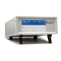
Model 425 Gaussmeter
Pin Description Pin Description
1 Monitor out 14 Ground
2 Internal use only 15 Ground
3 Internal use only 16 Ground
4 No connection 17 No connection
5 Internal use only 18 No connection
6 Internal use only 19 No connection
7 No connection 20 No connection
8 Relay 1 normally open 21 No connection
9 Relay 1 common 22 No connection
10 Relay 1 normally closed 23 No connection
11 Internal use only 24 No connection
12 Internal use only 25 No connection
13 Internal use only
TABLE 8-3 Auxiliary I/O connector details
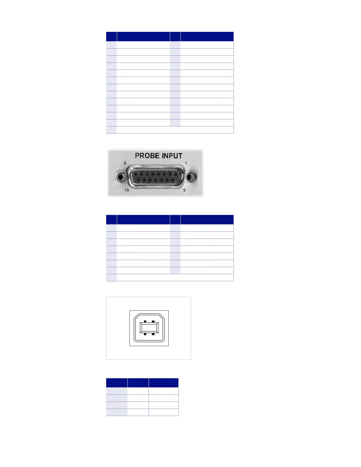
FIGURE 8-2 Probe input socket
Pin Description Pin Description
1 V input + 9 V input –
2 No connection 10 No connection
3 Internal use only 11 EEPROM GND
4 Internal use only 12 EEPROM VCC
5 Internal use only 13 EEPROM CLK
6 Internal use only 14 EEPROM DATA
7 No connection 15 I Hall –
8 I Hall +
TABLE 8-4 Probe input connector details
FIGURE 8-3 USB connector
Pin Name Description
1 VCC +5 VDC
2 D- Data –
3 D+ Data +
4 GND Ground
TABLE 8-5 USB connector details