3.8 Attaching a Hall Generator to the Model 425 27
| www.lakeshore.com
Monitor output: the Model 425 has a monitor output that provides an analog represen-
tation of the reading, and is corrected for probe offset and nominal sensitivity. The
monitor output has an output scale of ±3.5 V, which is proportional to the measured
field on the selected range. You can connect an oscilloscope or data acquisition sys-
tem to the monitor out to analyze the readings.
Relay 1:
the Model 425 has one mechanical relay designated as relay 1. The relay is
associated with the high and low alarms, or you can manually control it. Refer to
section 1.6.4 for voltage and current ratings for the relay. Refer to section 5.2.6 for
more operational details.
3.8 Attaching a
Hall Generator to
the Model 425
Connecting a Hall generator to the Model 425 requires a Lake Shore Model HMCBL-6
(2 m [6 ft]) or HMCBL-20 (6 m [20 ft]) cable assembly, which are sold separately. Each
Hall generator purchased from Lake Shore will come with a nominal field sensitivity
value. However, we recommend that the customer always check accuracy against a
reference field to verify the sensitivity value sent with the bare Hall generator.
Lake Shore has no control of the installation; therefore, the user must accept respon-
sibility for accuracy and compatibility.
In cryogenic applications, Manganin™ lead wire is frequently used because of its
thermal conductivity properties. Manganin™ wire is not usually acceptable for con-
nection to a Hall generator because the resistance of Manganin™ wire is often too
high. The gaussmeter current source is limited in compliance voltage. The Model 425
should not drive a load (Hall sensor, customer leads, and cable) greater than 30 ). In
cryogenic applications, Hall generators are normally connected using twisted pairs of
copper wire such as 34 AWG, Teflon® insulated wire.
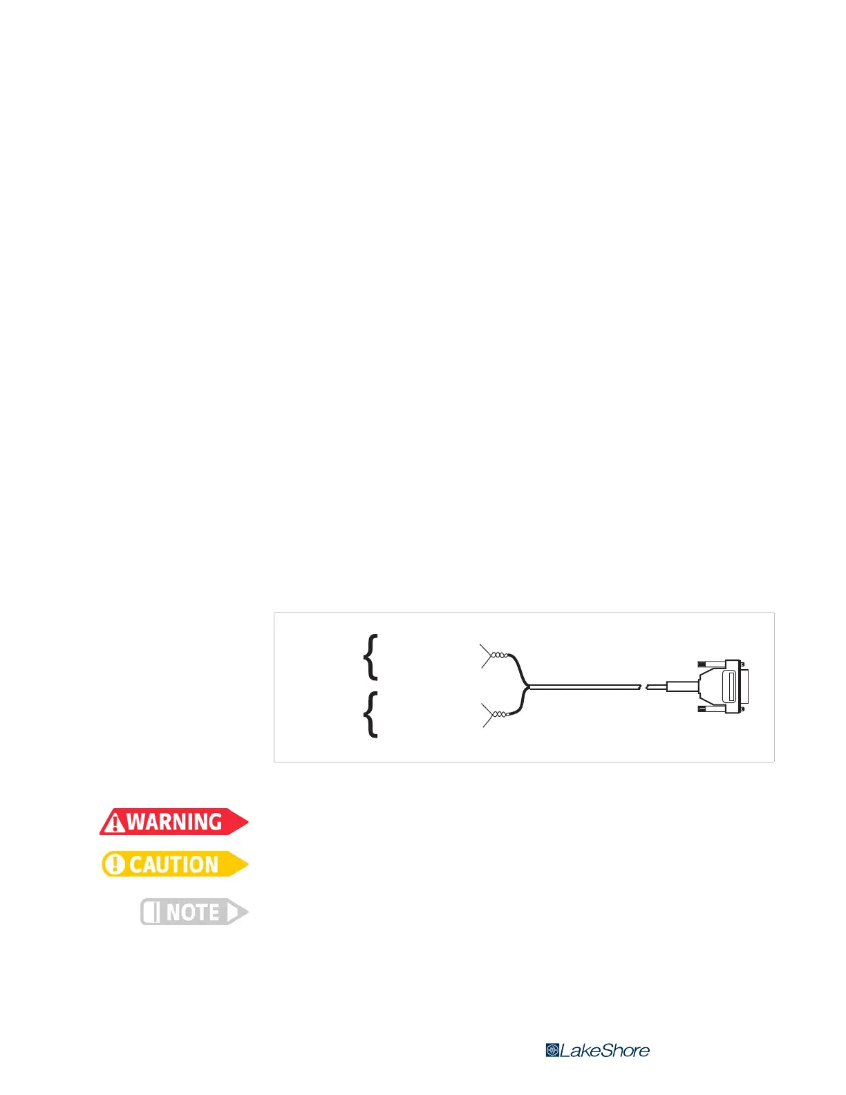
The HMCBL-XX cable has a 15-pin D-sub plug on one end for direct attachment to the
probe input socket on the rear panel of the Model 425 gaussmeter. The four leads,
illustrated in FIGURE 3-9, correspond to the four leads on the Hall generators. The
leads may be soldered directly to these wires. Once connections are made, refer to
section 5.5.1 for instructions on programming parameters into the internal EEPROM.
Accidental contact of Hall generators to hazardous live voltage can cause injury or death.
Lake Shore Hall generators are not designed for direct exposure to live voltage. Exposing
the Hall generator to live voltage can cause damage to the instrument.
Refer to the Lake Shore Magnetics Catalog for a list of compatible Hall generators manu-
factured by Lake Shore.
3.8.1 Polarity
If the control current enters the red lead (with +I
C
connected to the positive terminal
of the current supply), and the magnetic field direction B is as shown in section 2.4, a
positive Hall voltage will be generated at the +V
H
lead. Reversing either the current or
the magnetic field will reverse the output voltage.
FIGURE 3-9 Model HMCBL-XX user programmable cable accessory
Current to
sensor
Hall voltage
from sensor
Cable to gaussmeter
Green wire (-I
C
)
Red wire (+I
C
)
Blue wire (+V
H
)
Yellow wire (-V
H
)