8.5.2 P roduct Informa tion 65
| www.lakeshore.com
8.5.2 Product
Information
Product information for your instrument is also found in the Factory Reset menu. The
following information is provided:
D Firmware version
D Serial number
8.6 Error
Messages
The messages listed in TABLE 8-2 appear on the instrument display when it identifies
a problem during operation. The messages are divided into three groups. Instrument
hardware messages are related to the instrument’s internal circuits or non-volatile
memory. If one of these messages persists after power is cycled, the instrument
requires repair or recalibration. Measurement messages are most often associated
with over field conditions caused by an improperly selected field range, excessive
noise on the measurement leads, or a missing or invalid probe. If these messages per-
sist after proper configuration, the instrument may require repair. Illegal operation
messages remind the operator when a feature is locked out or the instrument is not
configured to support a feature.
8.7 Rear Panel
Connector
Definitions
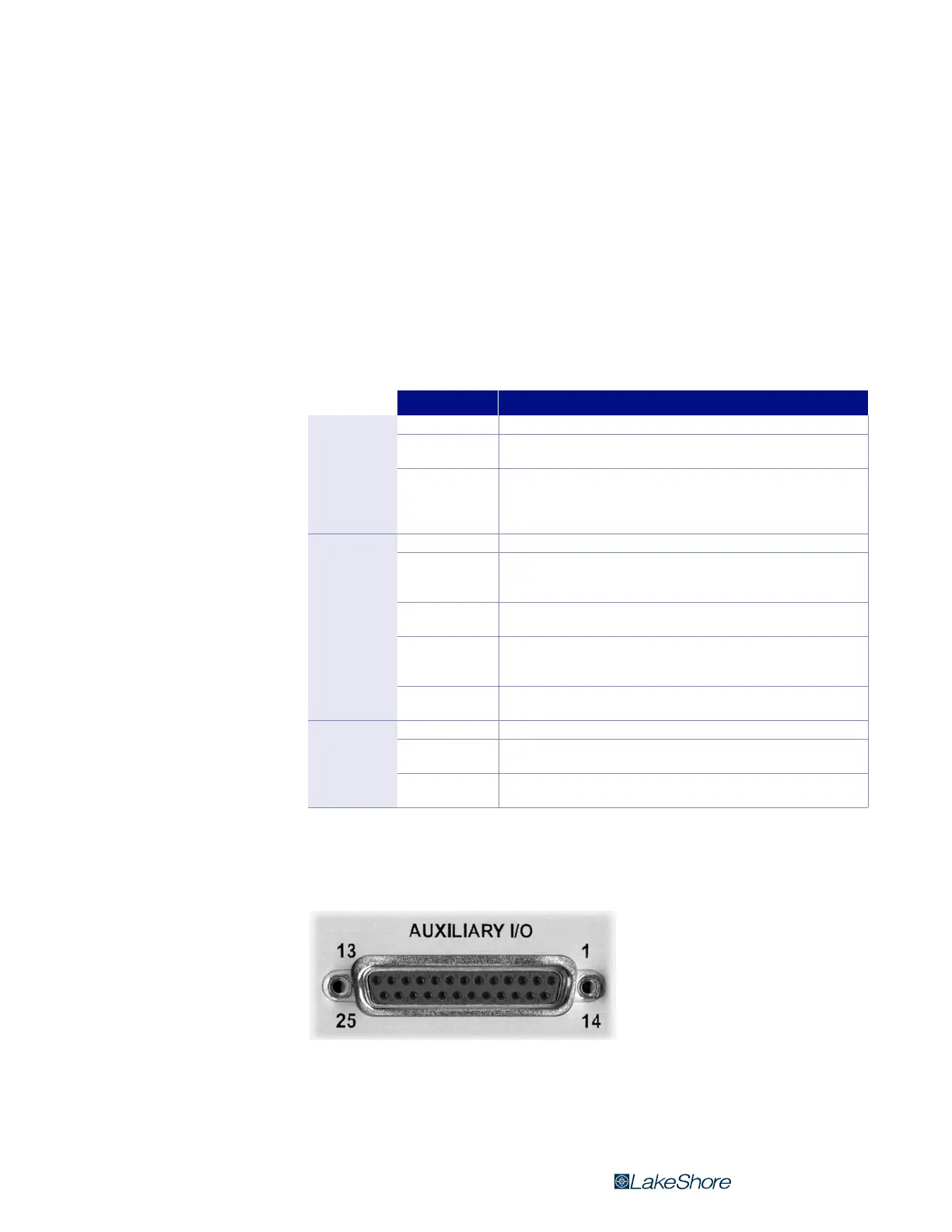
The auxiliary I/O, probe input, and USB connectors are shown in FIGURE 8-1 through
FIGURE 8-3 and defined in TABLE 8-3 through TABLE 8-5.
Message Description
Instrument
hardware
error messages
Defective RAM Internal RAM is defective and must be replaced.
Invalid EEPROM
EEPROM contents are corrupt, and parameter values will be reset to default.
Reoccurrence may indicate defective EEPROM.
Invalid calibration
Instrument has not been calibrated or calibration memory has been cor-
rupted. Recalibration is required for accurate measurements. Press the
Escape and Enter keys simultaneously to clear the message. The instrument
can still be used, but it may not be operating within specifications.
Measurement
errror
messages
No probe There is no probe attached or the attached probe is damaged.
Invalid probe
The detected probe does not contain calibration information. This is more
often the case when using a Hall generator. Press Enter to continue and refer
to section 5.5.1 to enter probe sensitivity.
Incompatible probe
A previous generation probe has been attached. Press Enter to continue.
Measurement uses only nominal probe sensitivity. Accuracy not guaranteed.
OL
The measured field is larger than the range. Increase the measurement range
or turn autorange on. Check probe zero. If error condition still exists, the probe
may be damaged.
Probe offset larger
than expected
The amount of adjustment required to set the probe to zero is greater than
normal for the probe model.
Illegal
operation error
messages
*LOCKED* A change was attempted with the keypad locked.
Invalid HMPEC
cable
Improper cable attached during the HMPEC programming process
(section 5.5.1).
Invalid HMCBL cable
Improper cable attached during the HMCBL programming process
(section 5.5.1).
TABLE 8-2 Model 425 error messages
FIGURE 8-1 Auxialiary I/O socket