26 cHAPTER 3: Installation
Model 425 Gaussmeter
If the exact orientation of the magnetic field is unknown, the proper magnitude is
determined by turning on max hold and slowly rotating the probe. As the probe turns
and the measured field rises and falls, its maximum value is held on the display. Make
note of the probe orientation at the maximum reading to identify the field orienta-
tion.
3.7 Auxiliary I/O
Connection
The auxiliary I/O connector is a 25-pin D-sub socket. This provides access to the mon-
itor output and relays. The mating plug and connector shell are included with the
Model 425. The pins are defined in TABLE 3-3.
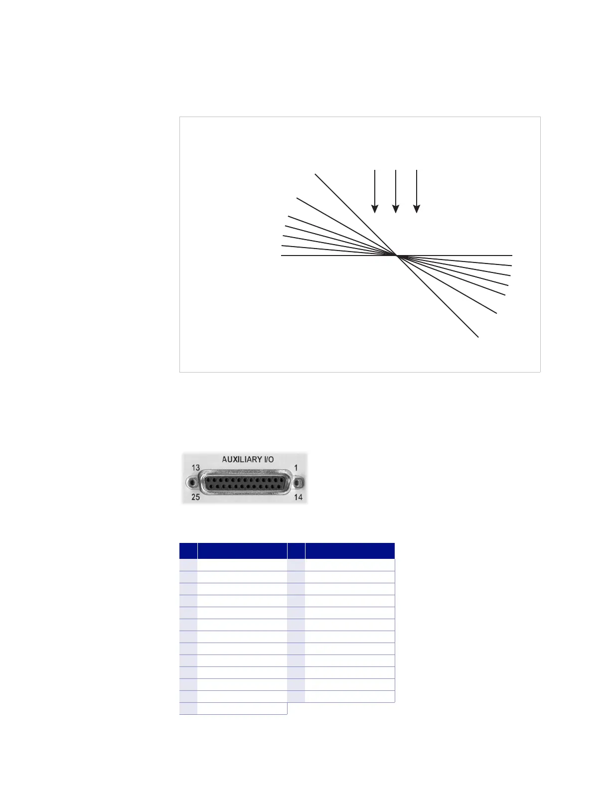
FIGURE 3-7 Effect of angle on measurements
Effect of angular variations on
percentage of reading error where
percent error = (1 – cos
ɲ
) 100
Deviation from
perpendicular (ɲ)
Error
+B
0% 0°
0.4%
5°
1.5%
10°
3.4%
15°
20°
30°
6.0%
13.4%
29.3%
45°
FIGURE 3-8 Auxiliary I/O socket
Pin Description Pin Description
1 Monitor out 14 Ground
2 Internal use only 15 Ground
3 Internal use only 16 Ground
4 No connection 17 No connection
5 Internal use only 18 No connection
6 Internal use only 19 No connection
7 No connection 20 No connection
8 Relay 1 normally open 21 No connection
9 Relay 1 common 22 No connection
10 Relay 1 normally closed 23 No connection
11 Internal use only 24 No connection
12 Internal use only 25 No connection
13 Internal use only
TABLE 3-3 Auxiliary I/O connector details