2.2.1 D C Measurem ent 11
| www.lakeshore.com
Chapter 2: Background
2.1 General
This chapter provides background information related to the Model 425 gaussmeter.
It is intended to give insight into the benefits and limitations of the instrument and
help apply the features of the Model 425 to a variety of situations. It covers flux den-
sity, Hall measurement, and probe operation. For information on how to install the
Model 425, please refer to Chapter 3. Instrument operation information is contained
in Chapter 4 and Chapter 5.
2.2 Model 425
Overview
The Model 425 gaussmeter is a highly configurable device with many built-in fea-
tures. It offers a DC mode to measure static or slowly changing fields, two different
modes to measure AC fields, narrow band and wide band, and a monitor output. Refer
to section 2.2.1 and section 2.2.2 for more information on these modes. To better
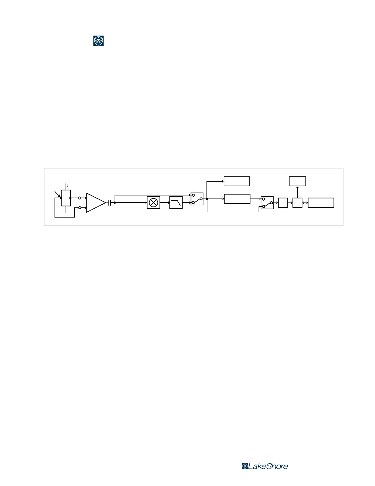
illustrate the capabilities of the gaussmeter, refer to the Model 425 system block dia-
gram, FIGURE 2-1.
2.2.1 DC Measurement
When in DC mode, the instrument uses a 100 mA, 5.4 kHz square wave excitation cur-
rent. The voltage that is generated by the Hall sensor goes through an AC coupled pro-
grammable gain stage. From there it passes through the product detector for
demodulation, a low pass filter, and the A/D converter. The digitized data is then sent
to the microprocessor. The monitor output will provide a DC voltage proportional to
the measured DC field. Refer to section 4.5.1 for the procedure to set the DC measure-
ment mode. Refer to section 5.3 for information on monitor output.
2.2.2 AC Measurement
Narrow band mode: in this mode, the instrument uses a 100 mA, 5.4 kHz square wave
excitation current. This type of excitation provides the benefit of noise cancellation
characteristics of the product detector, but it limits the maximum field frequency of
the Model 425 to approximately 400 Hz.
The voltage that is generated by the Hall sensor goes through an AC coupled pro-
grammable gain stage. From there it passes through the product detector for demod-
ulation, a low-pass filter, and an RMS-to-DC converter, before it is sent into the A/D
converter. The digitized data is then sent to the microprocessor. The monitor output
will provide an AC voltage proportional to the measured AC field. Refer to
section 4.5.2.1 for the procedure to set the narrow band AC measurement mode.
Wide band mode: in this mode, the instrument uses a 100 mA, DC excitation current to
drive the Hall sensor. This excitation type provides the greatest frequency range for
AC RMS measurements, up to 10 kHz. Since the signal doesn’t pass through the prod-
uct detector and low pass filter, it has a higher noise floor than narrow band mode.
FIGURE 2-1 Model 425 system block diagram
Gain
Low pass
filter
Product
detector
RMS-to-DC
converter
Computer
interface
µPA/D
Monitor out Display
Switch
Switch
Wide band
DC or narrow band
DC
AC modes
Ic
B
 Loading...