About X-431 Station
Diagnostics
Toolbox & Apps
FAQ
Initial Use
82
www.x431.com +86 755 8455 7891
LAUNCH
Station
User's Guide
A. DC voltage simulation
In Fig. Sensor-1, tap or click [Current voltage], then tap or click “+” or “-” to adjust the output voltage value.
Alternatively, user can also tap or click edit box, then use the on-screen keyboard to input the desired value
directly. After selecting or inputting the desired voltage based on the working characteristics of sensor, tap
or click the
button, then the diagnostic tool will begin to output the simulation voltages. Please note the
red probe is the output terminal of simulation voltage.
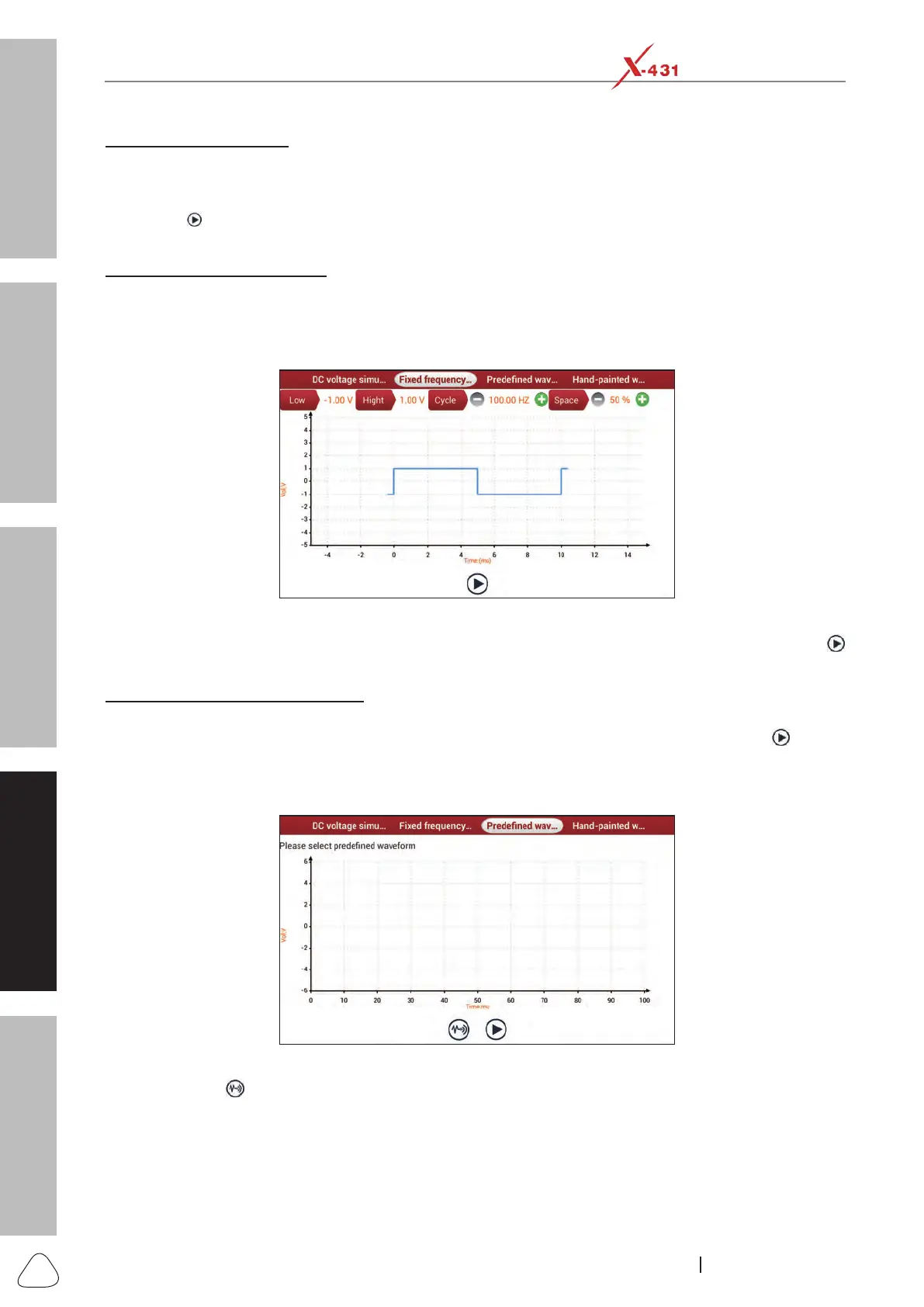
B. Fixed frequency simulation
This option enables you to simulate the square wave signal of pulse frequency of 0.1 ~ 15 kHz, amplitude
range of -5V ~ +5 V and duty cycle 10% ~ 90%.
In Fig. Sensor-1, tap or click “Fixed frequency simulation” to enter a screen similar to the following gure.
Fig. Sensor-2
Tap or click the setting option tab, then tap or click “+” or “-” to adjust the output,After setting, tap or click
to perform the test.
C.Predenedwaveformsimulation
X-431 Station provides some common sensor waveforms which have been predened to facilitate users
to simulate sensor signals. As long as you call out the predened waveform, then tap or click
to start
simulating output of corresponding sensor waveform and no more parameter settings of simulation
waveform are required.
In Fig. Sensor-1, tap or click “Predened waveform simulation” to enter the following screen.
Fig. Sensor-3
Here, tap or click
button, a screen similar to the following gure will appear.