Preparation Before Surgery
22
Leica HM500/Ref. 10 715 697/Version B
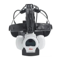
Attaching the strain relief device for the power cable
The strain relief device on the back of the Leica MLS500 light
s
ource prevents the power plug being pulled out accidentally.
➩Using a regular screwdriver, open the strain relief device (62).
➩Insert the power cable.
➩Press the strain relief device closed.
➩Before the power cable is removed the strain relief device
must be opened.
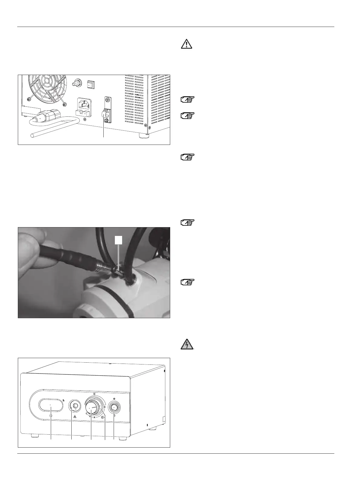
Connecting the fiber-optic light guide
➩ Insert the small end of the fiber-optic light guide into the
socket (23) on the microscope.
➩Insert the large end of the fiber-optic light guide into the
socket (58) on the front of the Leica MLS500 light source and
click it in place.
Caution 10
Damage to the fiber-optic light guide
➩Do not bend the fiber-optic light guide.
➩
Before using the fiber-optic light guide, check its
entire length for deformations, straightening where
necessary.
Switching the Leica MLS500 light source on/off
Avoid frequently switching the unit on and off since
this will greatly reduce the service life of the lamp.
Maximum brightness will not be reached until a few
minutes after switching on!
➩Press the rocker switch (61).
Once the display test has finished (4-5 seconds) the
Leica MLS500 light source starts up.
When the unit is switched off it is possible that the fans
will continue to run for a time to cool it down ("cool"
appears in the display (57)). Do not interrupt this cool-
ing-down phase by pulling out the power plug!
Adjusting the brightness
The rotary knob (59) operates a mechanical diaphragm which
sets the required quantity of light. This does not change the
color temperature.
To protect the eyes, adjust to no more than the maxi-
mum brightness required.
➩Turn the rotary knob (59) clockwise.
This increases the brightness.
➩Turn the rotary knob (59) counterclockwise.
This decreases the brightness.
Swinging filters in/out
Use original Leica filters only! Non-approved filters
could overheat and break.
Up to three filter settings can be controlled with the rotary
knob (60).
Positions A, B and C allow one of the three replaceable filters
(see page 43) to be selected and used. In position D, all filters
are swung out.
The light sources, including all of their accessories
(light guides, headset, etc.) must not touch the patient!
Before commissioning, be absolutely certain to read
this User Manual!
Take the instrument out of the packaging and place it on an
adequately sized horizontal surface. Make sure that the light
source cannot fall down, as this can result in injuries and dam-
age. The light source may be operated in a horizontal position
only.
If necessary, the light source can be held in place at both posi-
tions using M5 screws. Ensure that the screws do not penetrate
more than 5 mm into the housing. The clearance between the
two threaded bore holes is 244 mm. After fastening, ensure that
the light source is held in place securely!