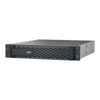
Figure 2. Rear view with dual, high availability, nodes
1 Top controller, node A 2 Bottom controller, node B
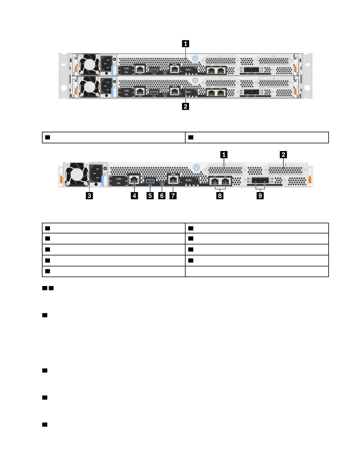
Figure 3. Rear view of controller nodes
1 Host Interface Card slot 1 2 Host Interface Card slot 2
3 Power Supply
4 RJ-45 console port
5 USB Type-A port 6 Micro-USB console port
7 1 GbE RJ-45 management port 8 10 Gbase-T Ethernet RJ45 ports (2)
9 25 GbE SFP28 connectors (2)
1 2 Host Interface Card (HIC) slots
You can find the Host Interface Card (HIC) slot numbers on the rear of each controller.
3 Power supply
The hot-swap redundant power supplies help you avoid significant interruption to the operation of the
system when a power supply fails.
On each power supply, there are multi-color status LEDs near the power cord connector. For information
about the status LEDs, see
“Rear view LEDs” on page 8.
4 RJ-45 console port
The RJ-45 console port connection provides serial access to the nodes BMC management network device.
5 USB Type-A port
The USB Type-A port is a Read-Only connection that can be used for ONTAP netboot and system updates.
6 Micro-USB console port
Chapter 2. System components 7
 Loading...