The Micro-USB console port connection provides serial access to the nodes BMC management network
device.
7 1 GbE RJ-45 management port
The RJ-45 console port connection provides 1 Gb Ethernet connectivity to the node for systems
management using the DM Storage Manager.
8 10 GbE RJ-45 console ports (2)
Each controller includes two 10 Gb Ethernet ports that are used for host I/O connectivity.
9 25 GbE SFP28 connectors (2)
Each controller includes two 25 Gb Ethernet ports that are used to provide node-to-node clustering or switch
node clustering on a DG5000.
Rear view LEDs
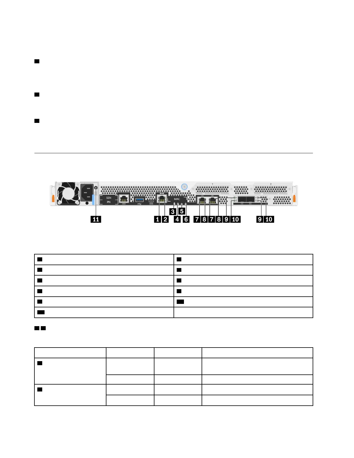
The illustration in this section shows the LEDs on the rear of the storage unit.
Figure 4. Rear view LEDs
Table 2. LEDs on the rear of the system
1 RJ45 management port link LED 2 RJ45 management port link LED
3 NVMEM discharge LED
4 Controller location LED
5 Controller attention LED 6 Controller activity LED
7 10 GbE port link LEDs (2) 8 10 GbE port activity LEDs (2)
9 25 GbE port link LEDs (2) 10 25 GbE port attention LEDs (2)
11 Power supply LED
1 2 RJ45 management port status LEDs
The RJ45 management port is a 1Gb Ethernet port that has two status LEDs.
Status LED Status Color
Description
1 RJ45 management port
link LED
On Green A link is established between the port and
some upstream device.
Off None No link is established.
2 RJ45 management port
activity LED
Blinking Green Traffic is flowing over the connection.
Off None No traffic is flowing over the connection.
8 ThinkSystem DG5000 Hardware Installation and Maintenance Guide




 To Next Page