The following table shows the cable connections for all configurations:
Configuration 2: (front drive bays and mid drive bays)
Front: three 8 x 2.5-inch SAS/SATA backplanes (BP 1, BP 2, and BP 3)
Mid: two 4 x 2.5'' NVMe backplanes (BP 5 and BP 6)
Co-
nfig.
Front BP Mid BP
Storage controller
PCIe switch
2
BP 1: NVMe 0–1, NVMe 2–3
NVMe 4–5, NVMe 6–7
Slot 1
C 0, C 1, C 2, C 3
BP 2: NVMe 0–1, NVMe 2–3
NVMe 4–5, NVMe 6–7
Slot 2
C 0, C 1, C 2, C 3
BP 3: NVMe 0–1, NVMe 2–3
NVMe 4–5, NVMe 6–7
Slot 4
C 0, C 1, C 2, C 3
BP 5: NVMe 0–1, NVMe 2–3
BP 6: NVMe 0–1, NVMe 2–3
Slot 5
C 0, C 1, C 2, C 3
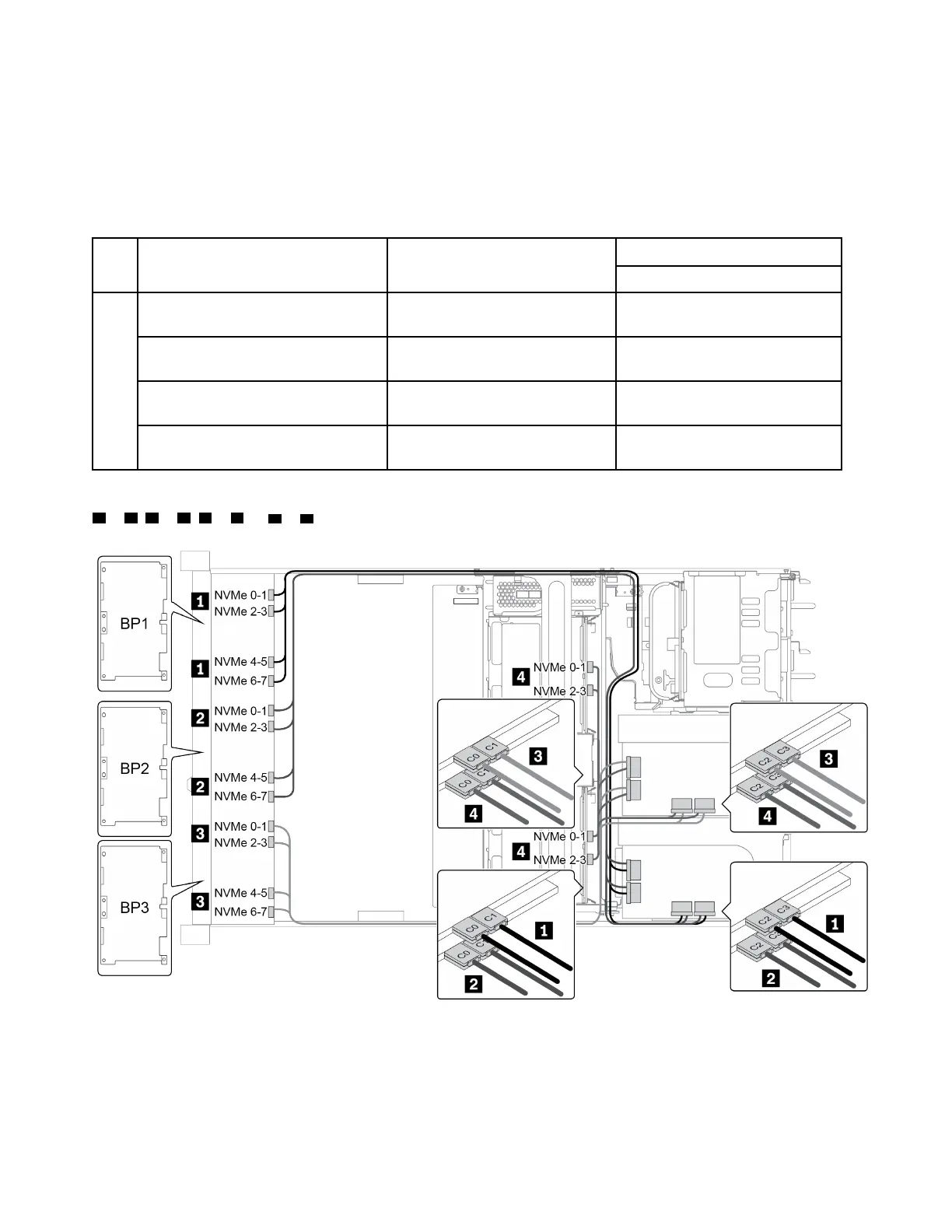
The following illustration shows the cable routing for the configuration 2. Connections between connectors:
1 ↔ 1 , 2 ↔ 2 , 3 ↔ 3 , ... n ↔ n
Figure 41. Cable routing for configuration 2
114 ThinkSystem SR665 Maintenance Manual

 Loading...


