16 x 2.5-inch front drive bays (8SAS/SATA+8NVMe)
This section provides cable routing information for the server model with 16 x 2.5-inch front drive bays
(8SAS/SATA+8NVMe).
The server model is configured with one 8 x 2.5-inch SAS/SATA backplane (BP 1) and one 8 x 2.5-inch
AnyBay backplane (BP 2). Below lists all supported configurations with these two front drive backplanes.
Note: The AnyBay backplane (BP 2) is used as pure NVMe backplane.
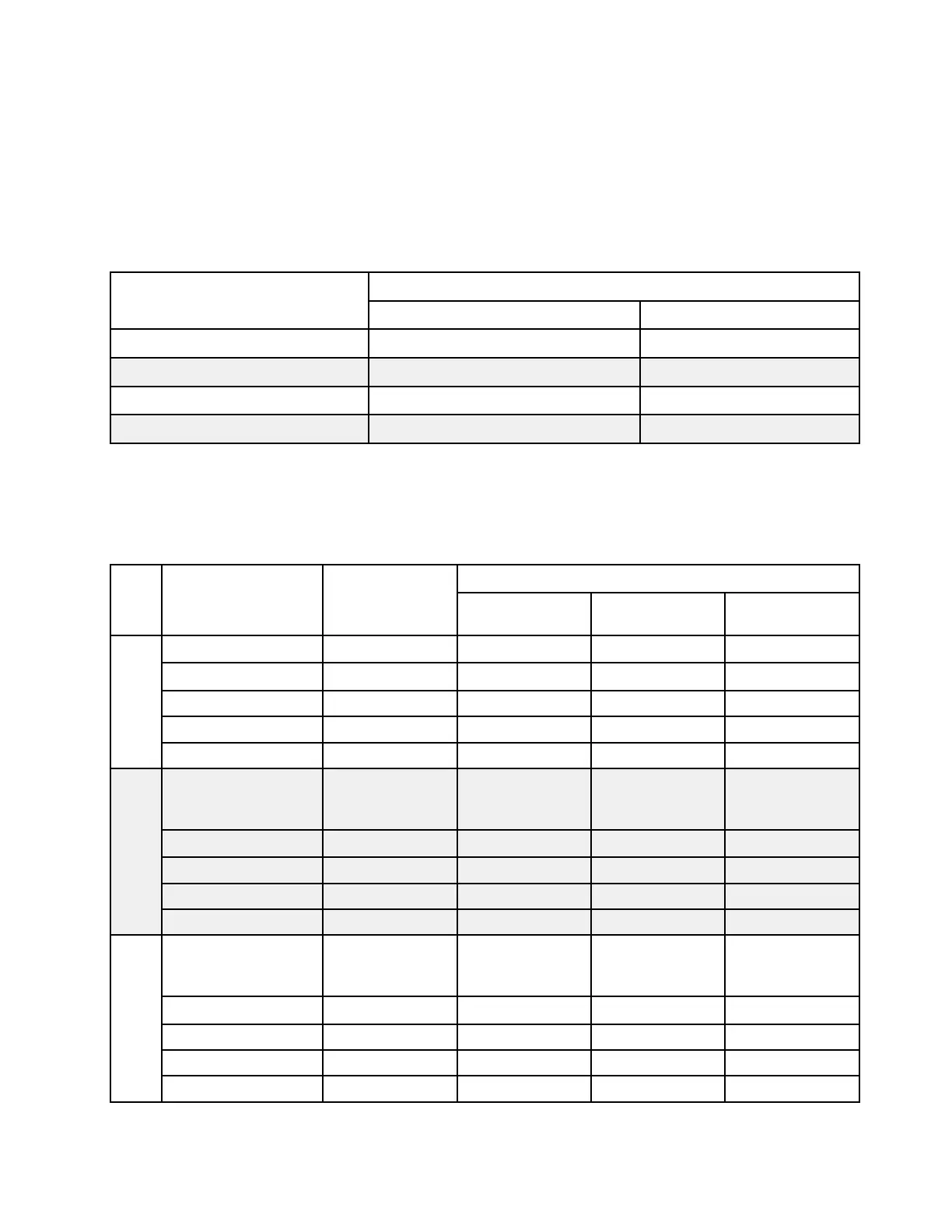
Configuration
Storage controller
Qty. Type
Config. 1
Config. 2
2 SFF 8i RAID/HBA
Config. 3
1 SFF 16i RAID/HBA
Config. 4
1 CFF 16i RAID/HBA
The following table shows the cable connections for all configurations:
Configuration 1, 2, 3, and 4: (front drive bays only)
Front: one 8 x 2.5-inch SAS/SATA backplane and one 8 x 2.5-inch NVMe backplane
Con-
fig.
Front BP
System board
Storage controller
SFF 8i RAID/HBA
SFF 16i RAID/
HBA
CFF 16i RAID/
HBA
1
BP 1: SAS
PCIe 4, PCIe 5
BP 2: NVMe 0–1
PCIe 1, PCIe 2
BP 2: NVMe 2–3 PCIe 3
BP 2: NVMe 4–5 PCIe 7
BP 2: NVMe 6–7 PCIe 8
2
BP 1: SAS
Gen 4: C 0
Gen3: C 0, C 1
BP 2: NVMe 0–1
PCIe 1, PCIe 2
BP 2: NVMe 2–3 PCIe 3
BP 2: NVMe 4–5 PCIe 7
BP 2: NVMe 6–7 PCIe 8
3
BP 1: SAS
Gen 4: C 0
Gen3: C 0, C 1
BP 2: NVMe 0–1
PCIe 1, PCIe 2
BP 2: NVMe 2–3 PCIe 3
BP 2: NVMe 4–5 PCIe 7
BP 2: NVMe 6–7 PCIe 8
Chapter 3. Internal cable routing 83