Rear components overview
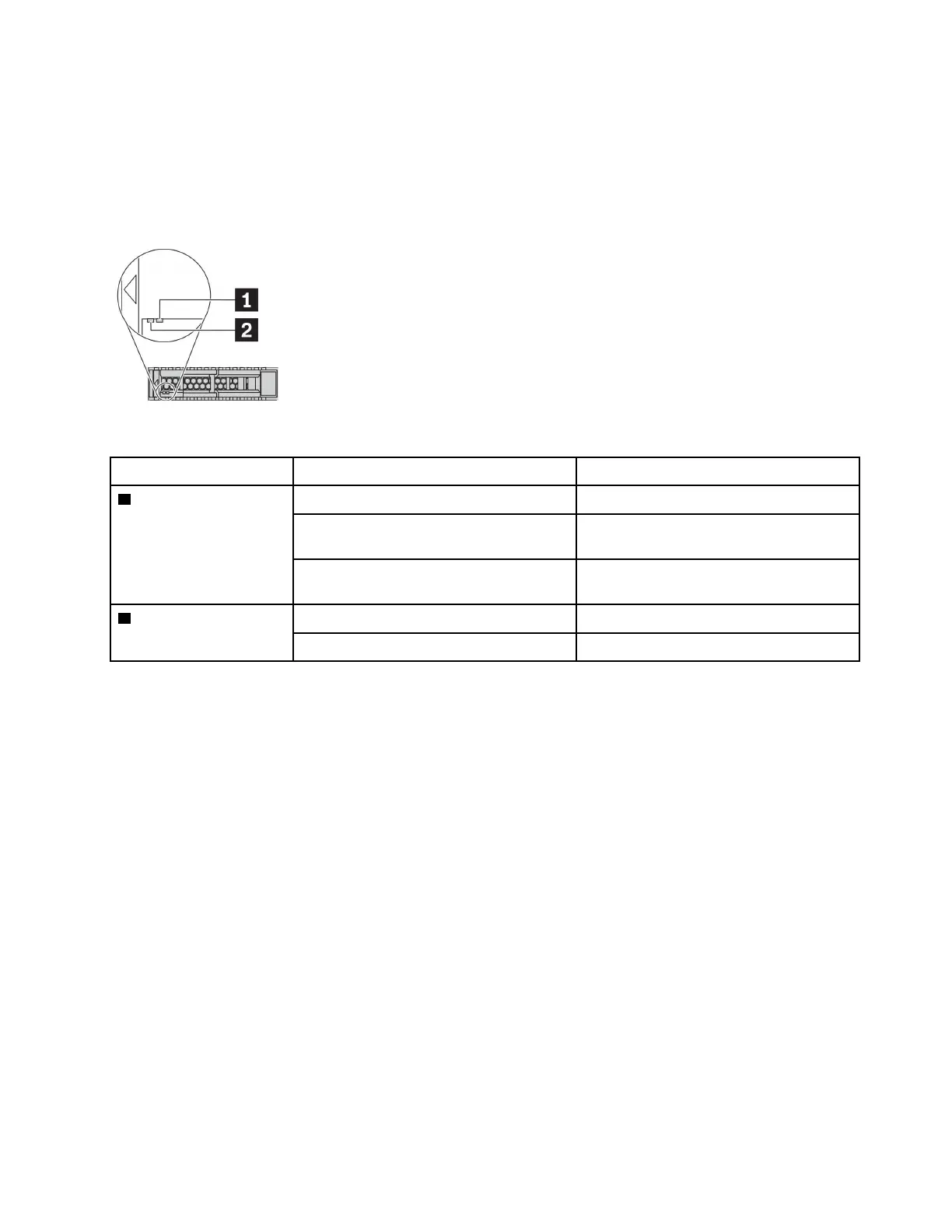
Drive LEDs
Each hot-swap drive comes with an activity LED and status LED and the signals are controlled by the
backplanes. Different colors and speeds indicate different activities or status of the drive. The following
illustration shows the LEDs on a Hard disk drive or solid–state drive.
Figure 7. Drive LEDs
Drive LED
Status
Description
1 Drive status LED (right) Solid yellow
The drive has an error.
Blinking yellow (blinking slowly, about one
flash per second)
The drive is being rebuilt.
Blinking yellow (blinking rapidly, about four
flashes per second)
The RAID adapter is locating the drive.
2 Drive activity LED (left) Solid green
The drive is powered but not active.
Blinking green The drive is active.
Ethernet connectors
The OCP 3.0 Ethernet adapter provides two or four extra Ethernet connectors for network connections.
One of the Ethernet connectors on the OCP 3.0 Ethernet adapter can also function as a management
connector using the shared management capacity. If the shared management connector fails, traffic can
automatically switch over to another connector on the adapter.
Hot-swap drives and drive bays
The drive bays on the front and rear of your server are designed for hot-swap drives. The number of the
installed drives in your server varies by model. When you install drives, follow the order of the drive bay
numbers.
The EMI integrity and cooling of the server are protected by having all drive bays occupied. Vacant drive
bays must be occupied by drive fillers.
NMI button
Press this button to force a nonmaskable interrupt (NMI) to the processor. By this way, you can make the
operating system halt (such as Windows Blue Screen of Death) and take a memory dump. You might have to
use a pen or the end of a straightened paper clip to press the button.
Chapter 2. Server components 39