Rear view LEDs
The illustration in this section shows the LEDs on the rear of the server.
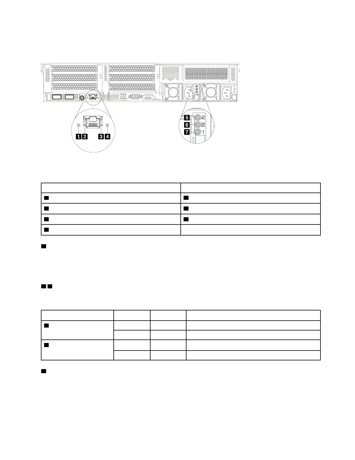
Figure 8. Rear view LEDs of the server
Table 18. LEDs on the rear of the server
Callout Callout
1 System ID LED
2 Ethernet link LED
3 Ethernet activity LED
4 System error LED
5 Power input LED 6 Power output LED
7 Power supply error LED
1 System error LED
The system error LED provides basic diagnostic functions for your server. If the system error LED is lit, one or
more LEDs elsewhere in the server might also be lit to direct you to the source of the error. For more
information, see “Diagnostics panel” on page 23.
2 3 Ethernet status LEDs
The BMC management connector has two status LEDs.
Ethernet status LED
Color Status
Description
2 Ethernet link LED Green On Network link is established.
None Off Network link is disconnected.
3 Ethernet activity LED Green Blinking Network link is connected and active.
None
Off The server is disconnected from a LAN.
4 System ID LED
The blue system ID LED helps you to visually locate the server. A system ID LED is also located on the front
of the server. Each time you press the system ID button, the state of both the system ID LEDs changes. The
LEDs can be changed to on, blinking, or off.
Chapter 2. Server components 41

 Loading...


