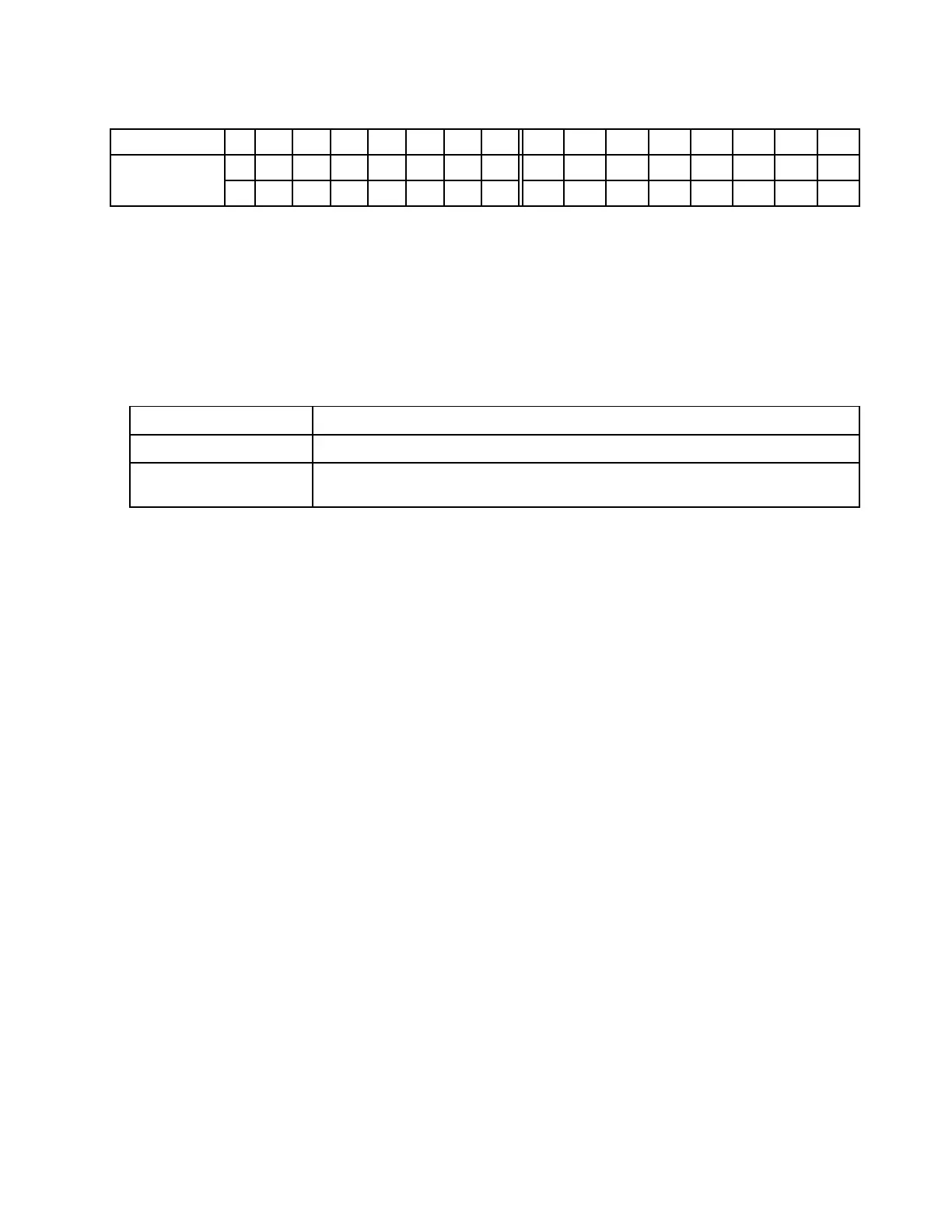
Table 30. Memory slot and channel identification
Channel
D1
D0 C1 C0
B1
B0
A1
A0 E0
E1
F0
F1
G0 G1 H0
H1
Slot number
16 15 14 13 12 11 10 9 8 7 6 5 4 3 2 1
32 31 30 29 28 27 26 25 24 23 22 21 20 19 18 17
Rules you need to follow when installing or replacing a DIMM.
• Slot:
– When a data bus daisy chain topology is used: populate DIMMs from farthest slot (slot 1) to closest
slot (slot 0) to the processor on a per-channel basis.
– When a data bus balanced tee route topology is used: populate DIMMs in either slot on a per-
channel basis.
Table 31. DIMM installation sequence
Number of processor Slot sequence
With one processor
14, 16, 3, 1, 10, 12, 7, 5, 13, 15, 4, 2, 9, 11, 8, 6
With two processors 14, 30, 16, 32, 3, 19, 1, 17, 10, 26, 12, 28, 7, 23, 5, 21, 13, 29, 15, 31, 4, 20, 2, 18, 9, 25,
11, 27, 8, 24, 6, 22
• Capacity:
DIMMs with different capacities (only two different capacities) can be mixed, install the one with the
highest capacity first.
• Rank:
DIMMs with different ranks can be mixed, install the one with the highest rank first.
• Frequency:
DIMMs with different frequencies can be mixed in the same channel.
• Voltage:
DIMMs with different operating voltage cannot be mixed. (The only supported DIMM voltage is 1.2V.)
• ECC/Non-ECC:
ECC and non-ECC DIMM cannot be mixed. (Non-ECC DIMM is not supported for the server.)
• DRAM:
x4 and x8 DRAM based DIMMs can be mixed, but not in the same channel.
• Type:
DIMMs of different base module types can be mixed, but not in the same channel.
• Vendor:
DIMMs from different vendors can be mixed in the same channel.
Install a memory module
Use this information to install a memory module.
About this task
Attention:
Chapter 4. Hardware replacement procedures 255