Code table
10
Function library
10.20
L
10.20-5
EDS82EV903-1.0-11/2002
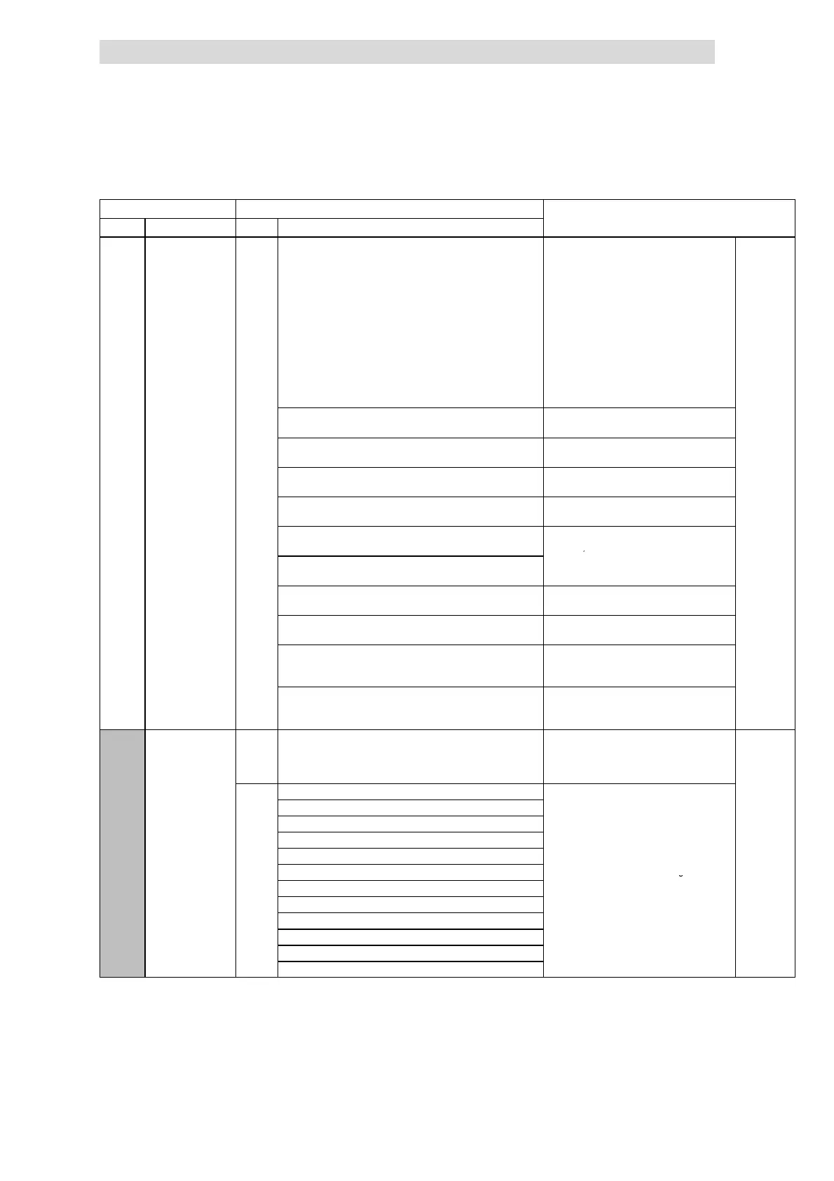
Code IMPORTANTPossible settings
No. SelectionLenzeName
C0005
v
Fixed configuration
analog input signals
0
Change under C0005 will b e copied to
the correspondin g subcode of C0412.
Free configuration under C0412 s ets
C0005 = 255!
Please observe for configurations with
frequency input:
• Activate the frequency input X3/E1,
X3/E2 with C0410/24 = 1.
• Delete all existing signal connections of
digital inputs used by the frequency
input in C0410.
• Frequency input configuration under
C0425 and C0426
^ 10.12-1
0 Setpoint for speed control via X3/8 or X3/1U,
X3/1I
1 Setpoint for speed control via X3/8 with setpoint
summation via frequency input
2 Setpoint for speed control via frequency input
with setpoint summation via X3/8
3 Setpoint for speed control via frequency input,
torque limit ation via X3/8 (power control)
4 Setpoint for sensorless torque control via X3/8,
speed limitatio n via C0011
Only active if C0014 = -5- (torque
selection)
5 Setpoint for sensorless torque control via X3/8,
speed limitation via freqency input
6 Controlled operation; setpoint via X3/8 with
digital feedback via frequency input
7 Controlled operation; setpoint via frequency input
X3/E1 with analog feedback via X3/8
200 All digital and analog input signals are sent via
the fieldbus module to FIF (e. g. INTERBUS oder
PROFIBUS-DP)
Sets C0410/x = 200 and C0412/x = 200
255 Free configuration under C0412 Only display
Do not change C0005 since settings under
C0412 can be lo st
C0007
v
uSEr
Fixed configuration
of digital inputs
Change under C0007 will b e copied to
the correspondin g subcode of C0410.
Free configuration under C0410 s ets
C0007 = 255!
^ 10.13-1
0
E4 E3 E2 E1
• CW/CCW = CW rotation/CCW rotation
0
CW/CCW DCB JOG2/3 JOG1/3
• DCB = DC-injection brake
1
CW/CCW PAR JOG2/3 JOG1/3
• QSP = Quick stop
2
CW/CCW QS P JOG2/3 JOG1/3
• P
R = Parameter set changeover (P
R1
ó P
R2
3
CW/CCW PAR DCB JOG1/3
–PAR1=LOW,PAR2=HIGH
4
CW/CCW QS P PAR JOG1/3
,
– The terminal must be assigned to the
5
CW/CCW DCB TRIP set JOG1/3
function ”PAR” in PAR1 and PAR2.
”
”
j6
CW/CCW PAR TRIP set JOG1/3
Configurations with ”P
R” are only
7
CW/CCW PAR DCB TRIP set
=
• TRIP set = external fault
8
CW/CCW QS P PAR TRIP set
9
CW/CCW QS P TRIP set JOG1/3
10
CW/CCW TRIP set UP DOWN