Pressure control
15
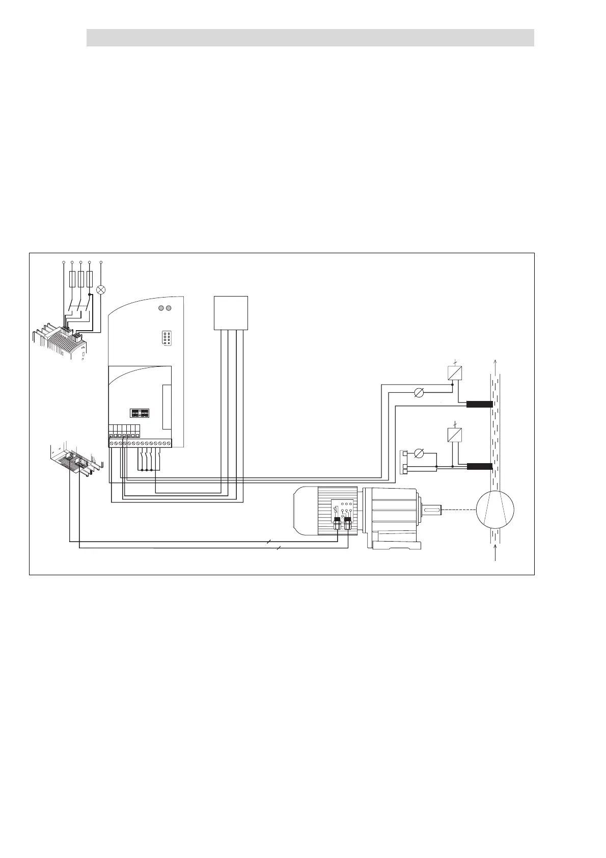
Application examples
15.2
L
15.2-4
EDS82EV903-1.0-11/2002
Jumper positions at application I/O
l
Jumper A in position 7-9 (actual pressure value 0 ... 10 V at X3/1U)
l Remove jumper B (setpoint selection via master current at X3/2I), (see
C0034)
l Jumper C in position 3-5 (actual pressure value output as current signal at
X3/62)
l Jumper D in position 2-4 or 4-6, since X3/63 is not assigned.
PE
W
2
U
2
V
2
U
PE
1
V
1
W
1
K12
K14
2
4
0...20mA
0 ... 20 mA
+
+
-
-
0 ... +10 V
0 ... +10 V
SPS
GND
JOG1
TRIP
4 ... 20 mA
L1
F1
K1
L2
L3
N
+-
~
2
+-
~
2
UP
DOWN
H/Re
CINH
62
1U
7
A2A1 7 7
A4
59 20 28 E1
E2
E3 E4
E5 E6
1U 1I
2U
2I
62
63 9
Application-I/O
1
2
T
2
T
1
Fig. 15.2-1 Principle wiring of a pressure regulation
Mains contactor
Analog display for actual pressure value
External power supply
2 conductor pressure sensor
3 conductor pressure sensor
, : use one pressure sensor only
Pump
Light on = ready for operation