t
t
t
0 Hz
30 Hz
10 Hz
20 Hz
40 Hz
50 Hz
60 Hz
0 Hz
30 Hz
10 Hz
20 Hz
40 Hz
50 Hz
60 Hz
-40 Hz
-60 Hz
-50 Hz
-30 Hz
-20 Hz
-10 Hz
t
t
t
t
t
t
t
t
0x2DDD
Running [50]
Stop active [53]
Run
Digital input 5 [15]
Digital input 4 [14]
Digital input 1 [11]
Constant TRUE [1]
Digital input 3 [13]
Digital input 2 [12]
Frequency setpoint selection
via analog input 1
(standard setpoint source)
Rotational direction reversed [69]
MOP setpoint down
Enable inverter
Output signals
Status signals
Output frequency
Invert rotation
MOP setpoint up
Activate MOP setpoint
Input signals
FunctionTrigger
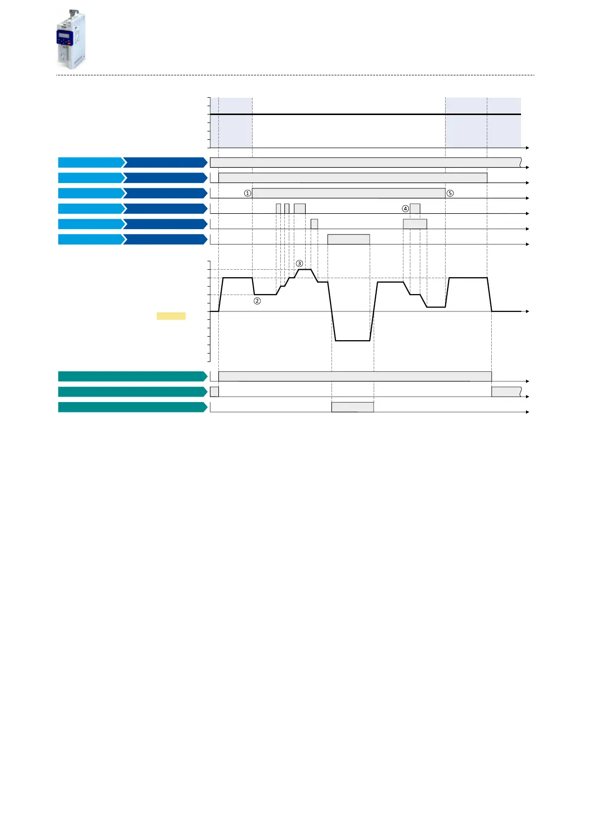
The status signals can be assigned to digital outputs. 4Conguraon of digital outputs ^ 415
①
Change-over from analog input 1 (standard setpoint source) to MOP setpoint.
②
The inial value for the motor potenometer funcon depends on the seng in 0x4003 (P413.00).
In this example, the "starng value" set in 0x4004:001 (P414.01) is used (here: 20 Hz).
③
The MOP setpoint is maximally increased to the maximum frequency set in 0x2916 (P211.00) (here: 50 Hz).
④
If "MOP setpoint up" and "MOP setpoint down" are requested at the same me, the MOP setpoint remains unchanged.
⑤
Change-over from MOP setpoint back to analog input 1 (standard setpoint source).
Flexible I/O conguraon
Setpoint change-over
Motor potenometer setpoint source (MOP)
381

 Loading...


