13.14.2 Analog input 2
Sengs for analog input 2.
Details
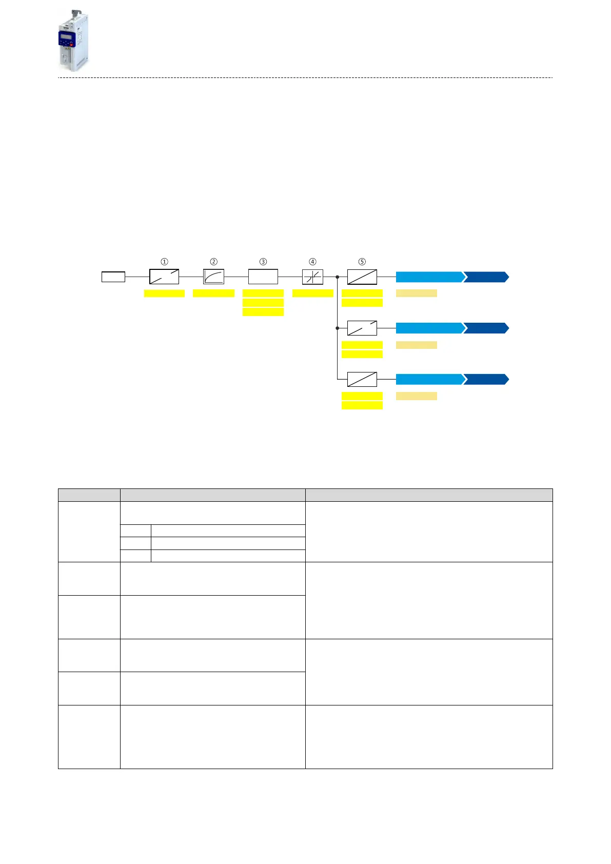
The analog input 2 can be used as setpoint source.4Selecon of setpoint source ^ 98
For the process controller, the analog input can be used for the feedback of the variable
(actual value) or speed feedforward control. 4Basic process controller sengs ^ 239
The following sengs are possible for the analog input:
•
Denion of the input range
①
•
Filter me for low-pass lters
②
•
Monitoring of the input signal
③
•
Dead band for eliminang the smallest signal levels
④
•
Denion of the seng range
⑤
AI2
0x2637:0020x2637:0080x2637:001
%
Hz
0x2637:006
0x2637:0030x2637:009
0x2637:010
0x2637:007
0x2637:004
0x2637:005
X3
%
V/mA
0x2DA5:002
0x2DA5:003
x y
<
>
0x2860:001
0x2860:002
[Hz]
[PID unit]
0x2637:011
0x2637:012
%
%
0x2DA5:004
0x2860:003
[%]
%
PID
unit
Analog input 2 [3]
Torque setpoint source
Analog input 2 [3]
Process controller setpoint source
Frequency setpoint source
Analog input 2 [3]
Diagnosc parameters:
•
The frequency value is displayed in 0x2DA5:002 (P111.02).
•
The process controller value is displayed in 0x2DA5:003 (P111.03).
•
The torque value is displayed in 0x2DA5:004 (P111.04).
For further details and conguraon examples, see chapter "Analog input 1". ^ 409
Parameter Name / value range / [default seng] Info
0x2637:001
(P431.01)
Analog input 2: Input range
(Analog input 2: AI2 input range)
Denion of the input range.
0 0 ... 10 VDC
1 0 ... 5 VDC
2 2 ... 10 VDC
0x2637:002
(P431.02)
Analog input 2: Min frequency value
(Analog input 2: AI2 freq @ min)
-1000.0 ... [0.0] ... 1000.0 Hz
Denion of the seng range for operang mode "MS: Velocity mode".
•
Direcon of rotaon according to sign.
•
The standard setpoint source for operang mode 0x6060 (P301.00) =
"MS: Velocity mode [-2]" is selected in 0x2860:001 (P201.01).
0x2637:003
(P431.03)
Analog input 2: Max frequency value
(Analog input 2: AI2 freq @ max)
Device for 50-Hz mains: -1000.0 ... [50.0] ... 1000.0 Hz
Device for 60-Hz mains: -1000.0 ... [60.0] ... 1000.0 Hz
0x2637:004
(P431.04)
Analog input 2: Min PID value
(Analog input 2: AI2 PID @ min)
-300.00 ... [0.00] ... 300.00 PID unit
Denion of the seng range for PID control.
•
The standard setpoint source for the reference value of PID control is
selected in 0x2860:002 (P201.02).
0x2637:005
(P431.05)
Analog input 2: Max PID value
(Analog input 2: AI2 PID @ max)
-300.00 ... [100.00] ... 300.00 PID unit
0x2637:006
(P431.06)
Analog input 2: Filter me
(Analog input 2: AI2 lter me)
0 ... [10] ... 10000 ms
PT1 me constant for low-pass lter.
•
By the use of a low-pass lter, the impacts of noise to an analog signal
can be minimised.
•
For an opmum lter eect, rst the noise frequency has to be deter-
mined. The me constant then has to be set so that it equals the
reciprocal value of the double frequency.
Flexible I/O conguraon
Conguraon of analog inputs
Analog input 2
413

 Loading...


