Process data transfer
Cyclic process data objects
Process data signals of Lenze controllers
9
l
56
EDSMF2178IB EN 3.0
9.3.1.2 Process data signals for 9300 servo inverter
The assignment of the process data for the 93XX controller can be changed by
reconfiguring the function blocks AIF−IN and AIF−OUT.
, 9300 system manuals
Here you can find detailed information on the function blocks and signal
configurations.
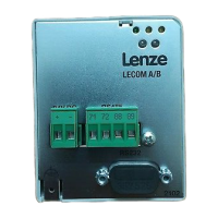
Function block AIF−IN
The function block AIF−IN determines the input data of the controller as data interface for
the EMF2178IB communication module.
Process data telegram to drive
User data (up to 8 bytes )
Byte 1 2nd byte 3rd byte Byte 4 Byte 5 Byte 6 7th byte Byte 8
Control
word
Low byte
Control
word
High byte
AIF−IN.W1
Low byte
AIF−IN.W1
High byte
AIF−IN.W2
Low byte
AIF−IN.W2
High byte
AIF−IN.W3
Low byte
AIF−IN.W3
High byte
^ 57
AIF−IN.W1 to AIF−IN.W3 depend on the signal configuration selected under code C0005.
Under code C0005 you can preconfigure the signals of the control word and the status
word.
In the controller, other signals can be assigned to AIF−IN.W1 to AIF−IN.W3. For this, the
function block configuration described in the 93XX System Manual is used.
Signal configuration
(C0005)
AIF−IN.W1 AIF−IN.W2 AIF−IN.W3 AIF−IN.D1
Speed control 1003 / 1013 / 1113 NSET−N
Speed setpoint
100 % = 16383
Not assigned
Not assigned Not assigned
Torque control 4003 / 4013 / 4113 MCTRL−MADD
Torque setpoint
100 % = 16383
LF master 5003 / 5013 / 5113 NSET−N
Speed setpoint
100 % = 16383
LF slave rail 6003 / 6013 / 6113 DFSET−A−TRIM
Phase trimming
DFSET−N−TRIM
Speed trimming
LF slave cascade 7003 / 7013 / 7113 DFSET−VP−DIV
LF factor
DFSET−A−TRIM
Phase trimming
cam profiler 1xxx3 YSET1−FACT
Not assigned
Positioning 2xxx3 Not assigned
vector control 1xx3 / 2xx3 / 3xx3 /
5xx3 / 100x3
NLIM−IN1
vector control 4xx3 NCTRL−MADD
vector control 6xx3 DFSET−A−TRIM DFSET−N−TRIM
vector control 7xx3 / 8xx3 / 9xx3 DFSET−VP−DIV DFSET−A−TRIM
vector control 100x3 NLIM−IN1
Not assigned
vector control 110x3 Not assigned
 Loading...