Electrical installation
StateLine C control terminals
Analog inputs and o utputs
6
226
EDS84ASC552 EN 10.0
Example circuit
"
GND-A
X3
O1U
E84AVSC...
GA A1I
A1U
AR
+10 V /
10 mA
"
U
GND-A
X3
O1U
E84AVSC...
GA A1I
A1U
AR
+10 V /
10 mA
8400SLC012 8400SLC011
X3
GND-A
O1U
E84AVSC...
GA A1I
A1U
AR
+10 V /
10 mA
int.
24E
GND-IO
GIO
24I
GND-IO
X4
B
"
=
-
+
"
GND-A
X3
O1U
E84AVSC...
GA A1I
A1U
AR
+10 V /
10 mA
8400SLC009 8400SLC013
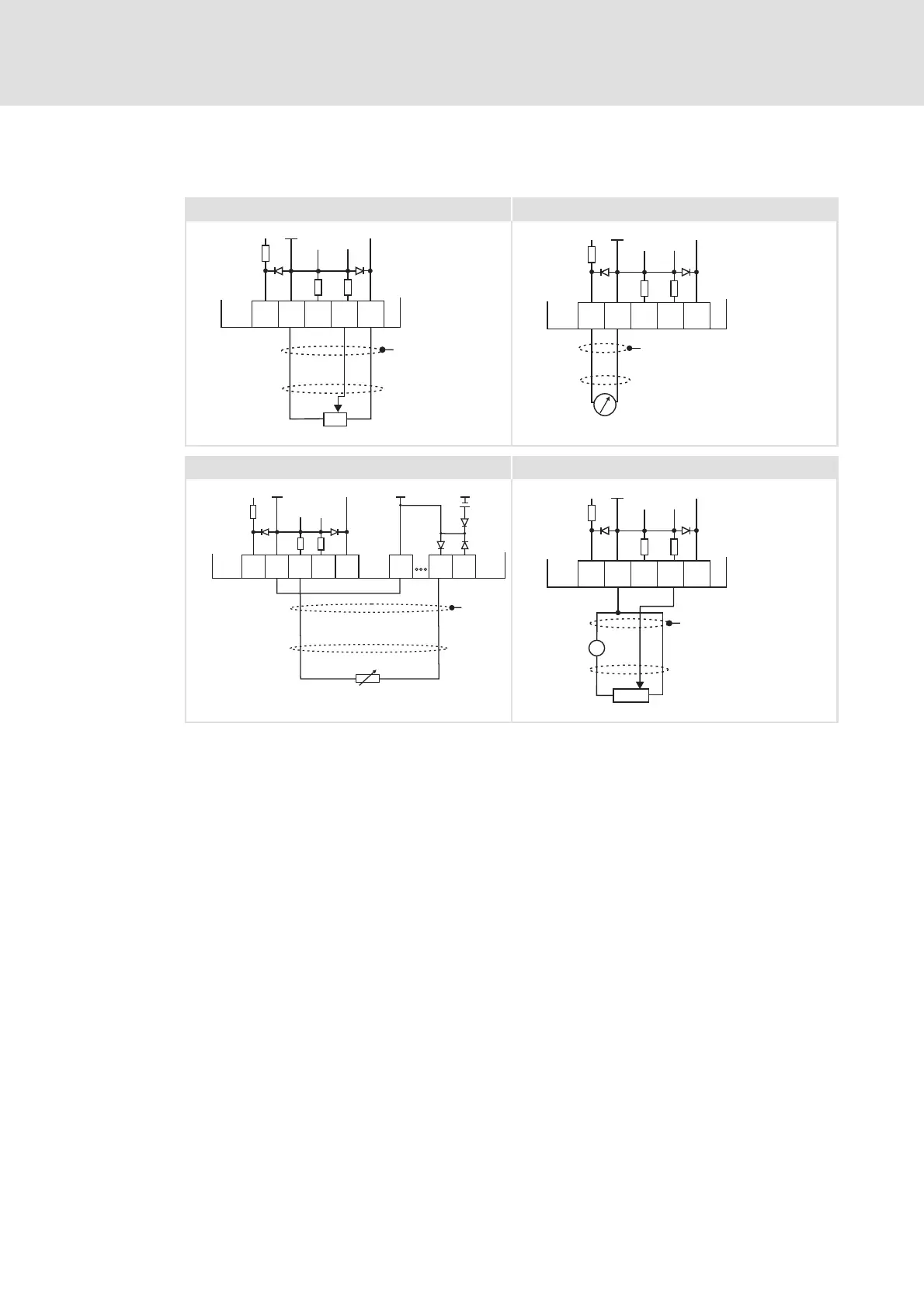
Fig. 6-35 Wiring examples of the analog inputs and outputs
Potentiometer with internal controller supply
Terminal assignment of the analog output signal, e.g. by a measuring
instrument
External master current selection based on a sensor signal 0 - 20 mA. If GA and
GIO are electrically connected, the digital cables have to be shielded as well.
Potentiometer with external supply
X3 Terminal for the analog inputs and outputs
X4 Terminal for the digital inputs and outputs
GA GND-A Ground reference potential for the analog inputs and outputs
GIO GND-IO Ground reference potential for the digital inputs and outputs
EMC shield connection
UMeasuringdevice
B Measuring transducer