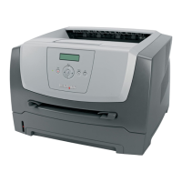
5-2 Lexmark™ E350d, E352dn
4512-420, -430
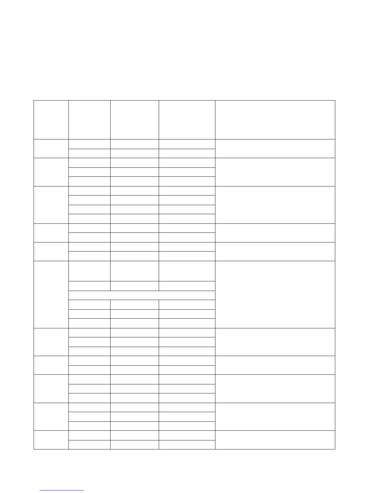
Controller card connector pin values
Note: See the wiring diagram at back of book.
These values were measured with all connections made (plugged) or with only one connector at a time
unplugged to expose the pins. Always disconnect and connect with the printer power off. Otherwise, the values
below may not match.
Connector Pin # Value
cableplugged
Value
cable unplugged
(if different)
Comments
J1 1 Signal Smart chip
2 Ground
J2 1 Less than 5 V dc Toner level sensor
2 Ground
3Signal
J3 1, 3, 5 Signal Operator panel
25Vdc
4, 7 Ground
63.3Vdc
J4 1 Ground Cooling fan
224Vdc
J5 1, 3 Signal LSU drive
2 Ground
J6 1, 2 5 V dc Less than 1 V dc
Front cover open switch
Cover closed
Cover open
3 Ground
10Vdc
25v
3 Ground
J8 2, 4, 7 Ground LSU
10 5 V dc
1, 3, 5, 6, 8, 9 Signal
J9 1, 2 24 V dc Reversing solenoid
2 Less than 1 V dc
J10 1 Less than 5 V dc Narrow media sensor
25Vdc
3 Ground
J11 1 Less than 5 V dc Exit sensor
25Vdc
3 Ground
J13 1 5 V dc Thermistor
2 Ground