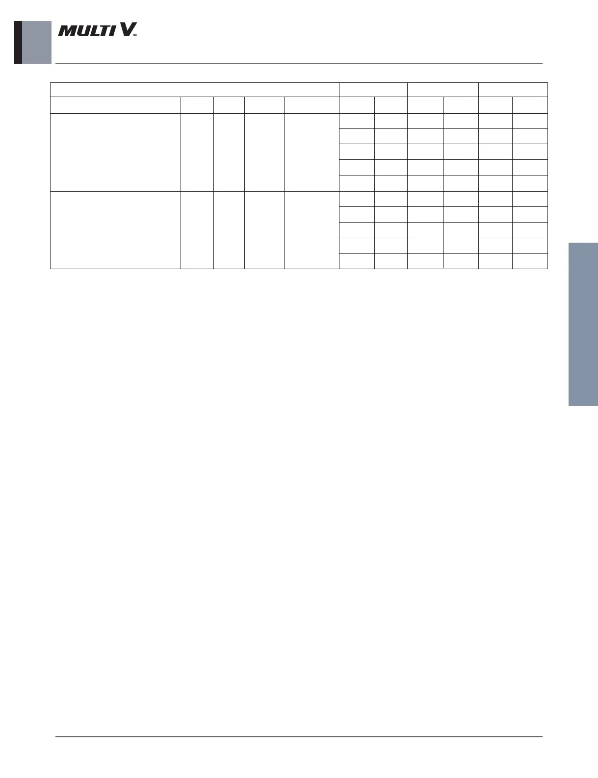
8. Electric Characteristics
Ceiling Cassette 1-Way _ 17
Indoor Units
Units
Model Type Hz Volts
Voltage Range
ARNU07GTU*4 TU
ARNU09GTU*4 TU
Max:264
ARNU12GTU*4 TU 50 220-240
Min:198
ARNU18GTT*4 TT
ARNU24GTT*4 TT
0.23 15 0.03 0.18 40 40
0.23 15 0.03 0.18 40 40
0.23 15 0.03 0.18 40 40
0.38 15 0.03 0.30 70 70
0.38 15 0.03 0.30 70 70
0.23 15 0.03 0.18 40 40
0.23 15 0.03 0.18 40 40
0.23 15 0.03 0.18 40 40
0.23 15 0.03 0.30 70 70
0.38 15 0.03 0.30 70 70
ARNU07GTU*4 TU
ARNU09GTU*4 TU
Max:242
ARNU12GTU*4 TU 60 220
Min:198
ARNU18GTT*4 TT
ARNU24GTT*4 TT
Power Supply IFM Input(W)
MCA MFA kW FLA Cooling Heating
Symbols:
MCA : Minimum Circuit Amperes (A)
MFA : Maximum Fuse Amperes(see note 5)
kW : Fan Motor Rated Output(kW)
FLA : Full Load Amperes(A)
IFM : Indoor Fan Motor
Note :
1. Voltage Range
Units are suitable for use on electrical system where
voltage supplied to unit terminals is not below or
above the listed range limits.
2. Maximum allowable voltage unbalance between
phase is 2%.
3. MCA/MFA
MCA = 1.25 x FLA
MFA ≤ 4 x FLA
( Next lower standard fuse rating. Minimum 15A)
4.
Select wire size based on the larger value on the MCA.
5. Instead of fuse, use Circuit Breaker.
 Loading...