6 _ Ceiling Cassette 2-way
Indoor Units
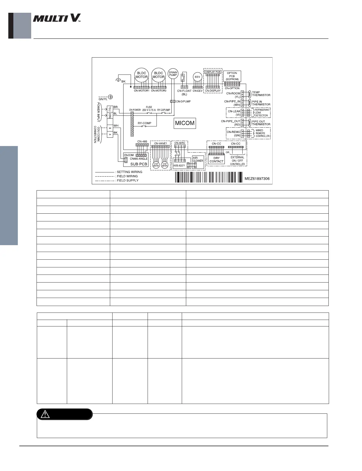
CONNECTOR NUMBER SPEC DESCRIPTION
CN-POWER AC Power supply AC Power line input for indoor controller
CN-MOTOR1 Fan motor output Motor output of BLDC
CN-MOTOR2 Fan motor output Motor output of BLDC
CN-D/PUMP Drain pump output AC output for drain pump
CN-485 Communication Connection between indoor and outdoor
CN-DISP Display Display of indoor status
CN-EEV EEV Output EEV Control output
CN-VANE1 Step motor Step motor output
CN-FLOAT Float switch input Float switch sensing
CN-PIPE/IN Suction pipe sensor Pipe in thermistor
CN-PIPE/OUT Discharge pipe sensor Pipe out thermistor
CN-ROOM Room sensor Room air thermistor
CN-REMO Remote controller Remote control line
CN-EXT External On/Off External On/Off signal input
TL Chassis
Dip Switch Setting Off On Remarks
SW3 GROUP Master Slave Group Control setting using Wired Remote Controller
Old Dry Contact Mode Setting
1. Variable : Auto/Manual Mode can be chosen by Wide wired
SW4 DRY CONTACT Variable Auto remote controller or Wireless remote controller
(When shipped from Factory ’ Manual Mode)
2. Auto : For Dry Contact, it is always Auto mode.
1. Duct model
-. OFF : Default(not operate continuosly )
-. ON : Fan operate continuosly
SW5 EXTRA 1 Off On 2. Cassette Model : No Function
3. Ceiling Suspended Model
-. OFF : Ceiling(default)
-. ON : Floor
For Multi V Model, Dip Switch 1,2,6,7,8 must be set OFF
That dip switch is used for the other model.
 Loading...