1.4 Operating Principle
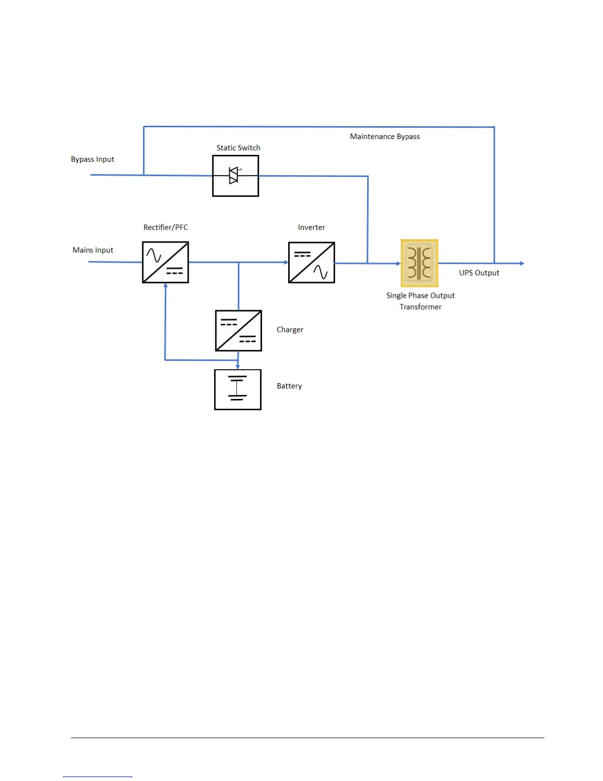
The operating principle of the UPS is shown in the figure 1-4.
Figure 1-4 UPS Operating Principle
1. The UPS is composed of mains input (main and bypass), rectifier/PFC, charger, inverter, bypass, battery, DSP
controller, single phase transformer, contactor and final output.
2. When the mains is normal, the rectifier will start, and the charger will charge the battery string. Before turning
on the UPS, the output voltage is bypass voltage, and the mains supplies power to the load through the bypass.
After turning on the UPS, the electronic transfer switch connects the inverter output to the load, and the mains
supplies DC power to the inverter through the rectifier/PFC circuit. The inverter then converts DC power into pure
sine wave AC power and supplies the AC power to the transformer connected to contactor. Final output is supplied
to load from transformer secondary through electronic transfer switch. Refer figure 1-3 for the position of contactor
and transformer.
3. When the mains is abnormal, the rectifier/PFC circuit boosts the battery voltage and supplies it to the inverter.
The inverter then converts it into pure sine wave AC power and supplies the AC power to the load through the
electronic transfer switch.
4. After the mains returns to normal state, the UPS will automatically transfer from Battery mode to Normal mode,
the mains supply DC power to the inverter through the rectifier/PFC circuit, and then the electronic transfer switch
supplies AC power to the load.