Vertiv|Liebert® S600 10kVA ~ 20kVA UPS | User Manual 22
2.4 Selecting Power Cables
I/O cables and battery cables are required for connection. When connecting the cables, you should follow the local
wiring regulations, take the environment situation into account, and refer to Table 3B of IEC60950-1.
The max. current in different operating modes is listed in Table 2-1, the recommended min. cable CSA is listed in
Table 2-2. Select the appropriate cables according to Table 2-1 and Table 2-2.
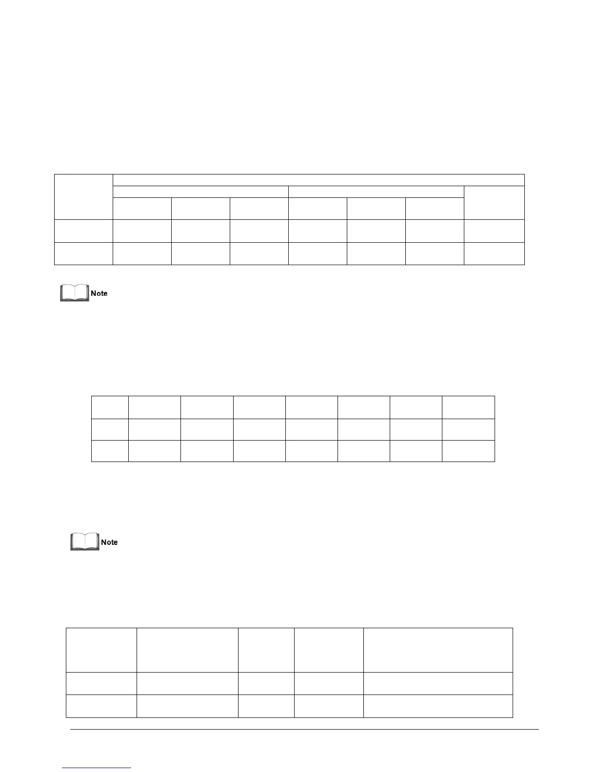
Table 2-1 Max steady state AC and DC current
Max.battery
discharging
current (A)
When the battery cables are selected, the maximum allowable voltage drop is 4Vdc according to the current value
shown in this table. Do not ring the cables to avoid increasing the electromagnetic interference (EMI).
1: The input mains current of the rectifier and the bypass.
2: Non-linear load (switch mode power) affects the neutral cable design of the output and the bypass. The neutral
cable current may exceed the rated phase current, up to1.732 times as large as the rated current.
Table 2-2 Single UPS cable CSA (unit: mm
2
, ambient temperature: 25 deg C)
The recommended I/O MCB capability of the UPS is listed in Table 2-4; select the MCBs according to your
requirements.
1. The UPS is high leakage current equipment, it is not recommended to use the MCB with leakage current
protection.
2. The specified upstream breakers below are required to obtain the conditional short-circuit current rating, Icc
at 10kA symmetrical rms. The specified upstream breakers should comply with an IEC 60947 series Standard.
Table 2-3 UPS I/O MCB Selection
Recommended
capability of input
external MCB
Battery
Fuse/MCB
Selection
Recommended
capability of
output external
MCB
Recommended
capability of
Maintenance bypass external
MCB
63A (mains)
125A (bypass)