3.3 Connecting Power Cables
Each single UPS of the parallel system needs to configure the MCB and cables respectively, refer to 2.4 Connecting
Power Cables for the specification. The recommended configurations of the total power cables are listed in Table 3-1
and Table 3-2 for the parallel system.
3.3.1 Connecting Power Cables
The power cables of the UPS are connected to the I/O terminal block of the rear panel of the UPS, the layout of the I/O
terminal block is shown in 2.6.1 Connecting I/O Cables.
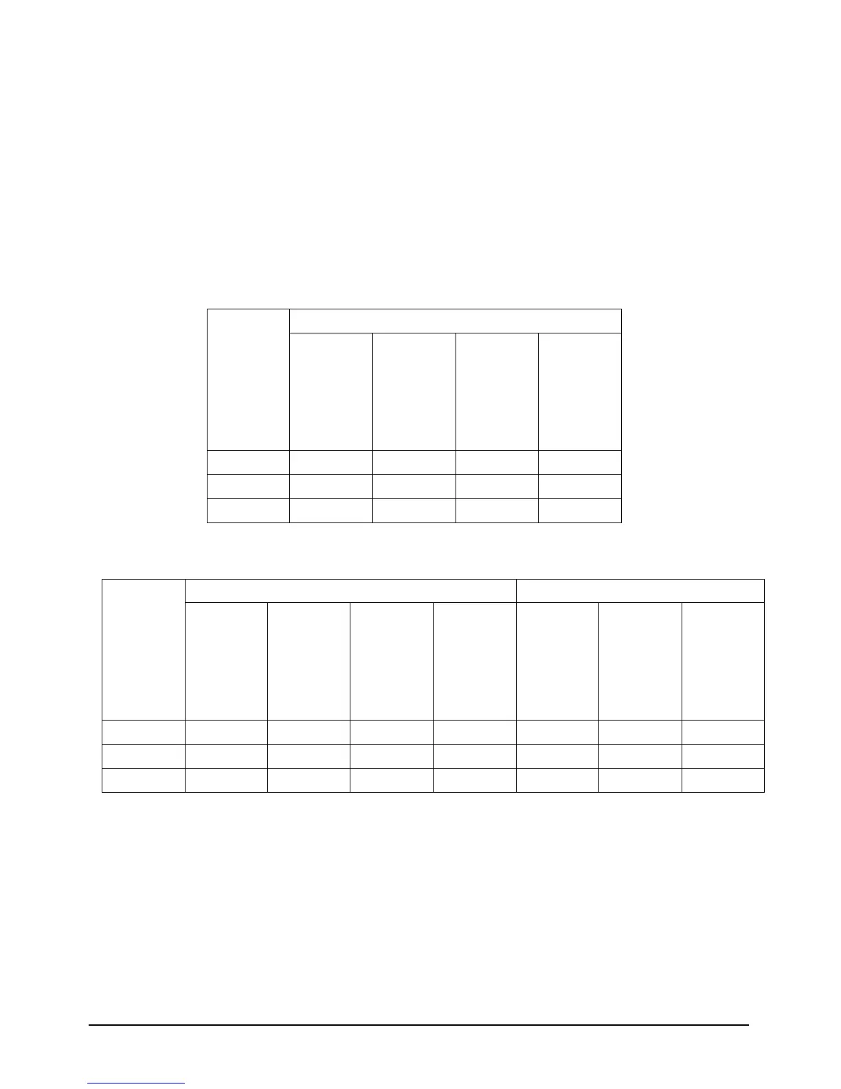
Table 3-1 Input & Output cable CSA for 10 kVA parallel system (unit:mm
2
, ambient temperature: 25 deg C)
Table 3-2 Input & Output cable CSA for 20 kVA parallel system (unit:mm
2
, ambient temperature: 25 deg C)
3.3.2 Connecting Parallel Cables
The parallel system provides parallel cable option. The parallel cables form a ring connection through the parallel ports
on the rear panel of the UPS. Taking 20kVA model for example, the cable connection schematic diagram of 3 + 1
parallel system is shown in Figure 3-1.