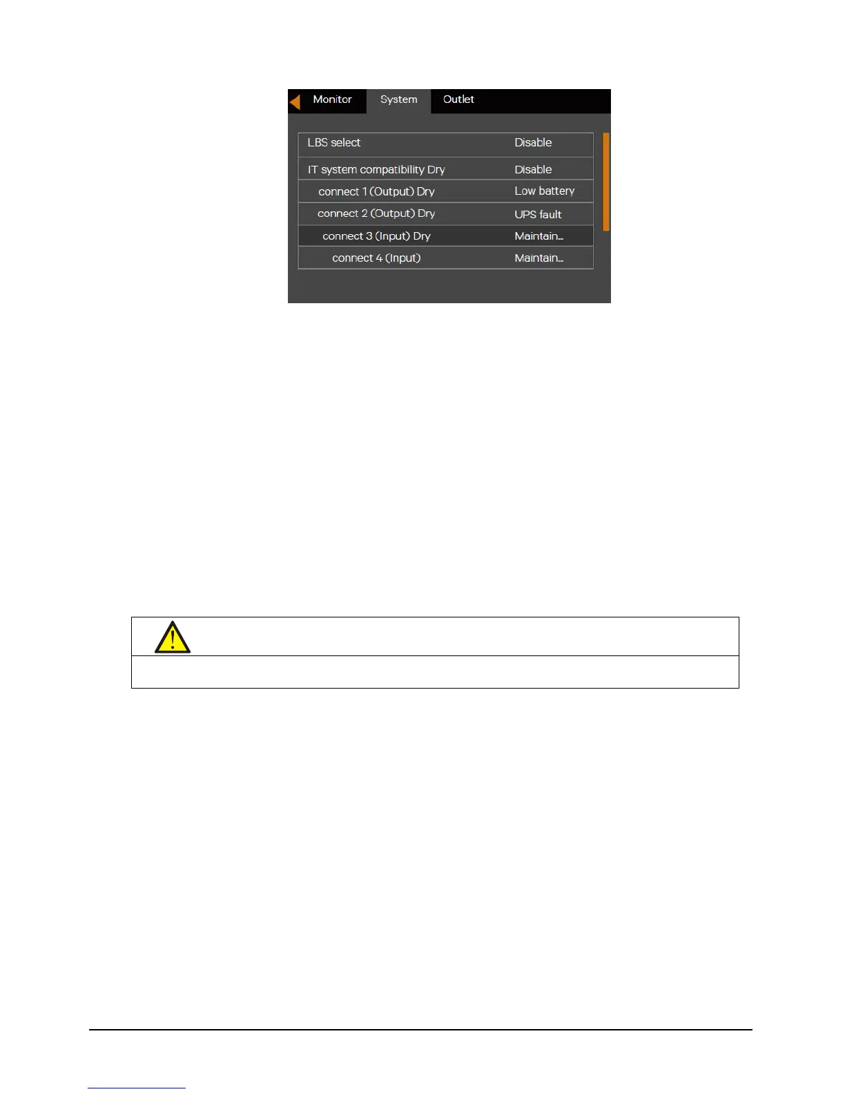
Figure 5-4 Changing dry contact 3 to “Maintain Mode”
2. Connect one end of the maintenance bypass signal cable to Dry Contact Port 3 of the UPS and the other end to the
NO/NC Auxiliary contact.
3. Remove the screws securing the Bracket of the maintenance bypass switch.
4. Turn Off Inverter.
5. Confirm that the UPS has transferred to internal bypass mode.
6. After confirmation, close the maintenance bypass switch
Note: Dry contact port 4 can achieve the same function as dry contact port 3 via the steps mentioned above.
5.4.3 Transfer from Maintenance Bypass to Inverter Mode
After UPS maintenance, you can use this procedure to transfer the load from the maintenance bypass to the inverter.
1. Close the mains input MCB and bypass input MCB on the rear panel of the UPS. The UPS will turn on and operate in
Bypass mode.
2. Confirm that the UPS is in Bypass mode, then close the output MCB on the rear panel of the UPS.
3. Open the maintenance bypass MCB on the rear panel of the UPS.
4. Fix Bracket of the maintenance bypass switch to its original position, then fasten the fixing screws.
5. Press the power button, and the UPS transfers to Inverter mode.
5.5 REPO
Located at rear of the UPS, the REPO port is designed to switch off the UPS in emergency conditions (such as fire,
flood). The system will turn off the rectifier, inverter and stop powering the load immediately (inverter and bypass
output included), and the battery stops charging or discharging. Just unplug the terminal connecting to the REPO if
you need emergency power-off.
If the mains input is present, the UPS control circuit will remain active; however, the output is closed. To remove all