LightLas 532 – Operator's Manual Rev. No 01 Page 56 of 115
All the items above and the rest of the system should be unpacked from their cartons
and carry cases and inspected for transportation damage and general condition.
Extreme care do not to touch the optic lens or parts and make sure all the items are
available.
The System consist of two major parts as follows:
LDU system (Slitlamp: Integrated or Attachment / LIO / Endoprobe)
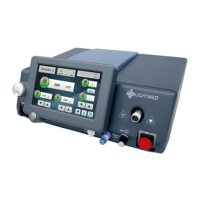
Console
LDU Systems
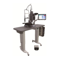
5.4.1 Slitlamp Integrated LDU
Prior to install the Slitlamp Integrated system, ensure all the corrected setup and
equipment are in placed to proceed the installation steps.
System Part(s):
Upper Arm Housing
Lower Base Housing
Table top
Accessories (binocular, cover, chinrest, and target rod)
Procedures:
1. Unpack all the packaging items from the cartoon box
2. Lay the ready to go table on the final destination location (well level) and ensure all
the accessories are installed including rail and joystick slide pad (refer to fig. 5.4)
3. Ensure the voltage and fuses rate setting are set up correctly, as default setting is
230VAC (refer to fig. 5.5a-d)
4. Take the Slitlamp upper arm housing and lower base housing with cross-slide shaft
assembled (refer to fig. 5.6)
5. Assembled the upper and lower housing together by securing the screw at rear
end of lower housing (refer to fig. 5.7)
6. Position the Slitlamp ass’y back to the gear rail and gently wheel it back and forth
to get it smooth out
7. Ensure the Slitlamp ass’y is horizontally parallel in x-axis
8. Place the gear cover
9. Install the Chinrest ass’y and connect the fixation lamp to the source box and plug
in the source power connection (refer to fig. 5.5a)